
Description
Hard-Numbers: Technical Specifications
- Functional Acronym: TCPS (Turbine Control Power Supply Board)
- Board Variant: G1 variant with PE suffix (specific hardware configuration)
- Revision: A (Board Revision A)
- Suffix: PE (configuration-specific designation)
- Core Function: Power distribution and conditioning for control system
- Input Power: Typically 125 V DC or 250 V DC input from external power sources
- Output Voltages: Multiple regulated DC output voltages (typically +5 V DC, ±15 V DC, +24 V DC)
- Power Capacity: Sufficient power capacity for multiple control boards
- Voltage Regulation: Precision voltage regulation for sensitive control electronics
- Current Limiting: Current limiting and protection features
- Overvoltage Protection: Overvoltage protection for output circuits
- Undervoltage Detection: Undervoltage monitoring and detection
- Power Sequencing: Controlled power sequencing for system startup
- Isolation: Electrical isolation between input and output circuits
- Diagnostic Features: Power status monitoring and fault detection
- LED Indicators: Multiple LED indicators for power status, faults, output voltages
- Dimensions: Standard Mark V board form factor (typically 3″ H × 11.5″ W)
- PCB Coating: Normal coating (non-conformal)
- Manual: GEH-6230 (Turbine Control Power Supply Board Manual) – PE supplement

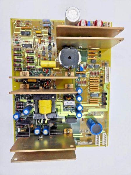
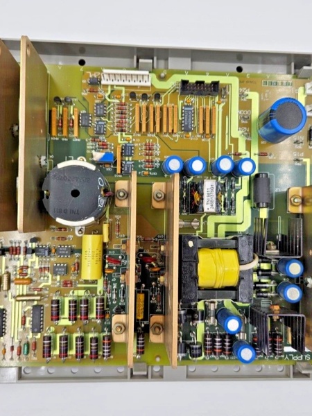
GE DS200TCPSG1APE
The Real-World Problem It Solves
The Mark V control system requires reliable, conditioned power distribution to operate all control boards, processors, interface boards, and associated electronics consistently and safely. The DS200TCPSG1APE (Turbine Control Power Supply Board – G1 Variant, Revision A with PE suffix) provides this critical power distribution and conditioning capability with PE-specific configuration features for particular applications or power requirements. The PE suffix indicates a specialized hardware configuration optimized for specific power distribution requirements, which may include particular input voltage ranges, enhanced output capacity, improved regulation characteristics, or application-specific protection features. The board converts external power sources into multiple regulated DC voltages required by various Mark V control system components. The PE configuration may include features tailored for specific turbine applications such as particular input power sources, enhanced load capacity, specialized sequencing requirements, or improved reliability features. Without this board, the Mark V control system would lack conditioned power distribution with PE-specific capabilities, potentially limiting system capabilities or reducing reliability for PE-configured applications.
Where you’ll typically find it:
- Power supply racks in Mark V control cabinets
- Turbine控制 systems requiring PE-configured power distribution
- Systems with specific input power or output capacity requirements
- Power generation facilities with complex power architectures
- Combined cycle plants requiring specialized control system power
- Applications requiring PE-specific power distribution capabilities
Bottom line: PE-configured power supply distribution board—providing specialized regulated, conditioned power to Mark V control system components with enhanced features for specific application requirements.
Hardware Architecture & Under-the-Hood Logic
The DS200TCPSG1APE (G1 Variant, Revision A with PE suffix) is the Turbine Control Power Supply Board for the Mark V control system, serving as the power distribution and conditioning center with PE-specific configuration features. The PE suffix designates a specialized hardware configuration optimized for specific power distribution requirements, which may include particular input voltage ranges, enhanced output capacity, improved regulation characteristics, or application-specific protection features. The board receives input power from external DC power sources and processes it through input filtering, surge protection, and isolation circuits. The filtered input power is then routed to multiple DC-to-DC converter modules that generate the regulated output voltages required by Mark V control system components. The PE configuration may include specialized converter modules, enhanced filtering, improved regulation circuits, or application-specific protection features that differ from standard TCPS configurations. Each output voltage is individually regulated, with current limiting circuits protecting against overloads. Overvoltage protection circuits clamp output voltages to safe levels, while undervoltage detection circuits monitor output voltages and signal low voltage conditions. The board includes power sequencing capabilities to ensure controlled startup of control system components. Diagnostic circuits monitor power status, output voltages, currents, and fault conditions, providing status information through LED indicators and communication interfaces.
Signal flow:
- Input power from external DC source enters TCPS-PE through input connectors
- PE-specific input protection circuits provide enhanced overcurrent protection and transient suppression
- PE-specific input filtering circuits provide enhanced noise and ripple removal
- Isolation circuits provide electrical separation from external power source
- Filtered input power is distributed to PE-specific DC-to-DC converter modules
- +5 V DC converter generates regulated +5 V DC for digital logic circuits
- +15 V DC converter generates regulated +15 V DC for analog circuits
- -15 V DC converter generates regulated -15 V DC for analog circuits
- +24 V DC converter generates regulated +24 V DC for field devices
- Each output has PE-specific current limiting circuits for enhanced protection
- Overvoltage protection circuits clamp output voltages to safe levels
- Undervoltage detection circuits monitor output voltages
- PE-specific power sequencing circuits control startup order of output voltages
- Diagnostic circuits monitor power status and fault conditions
- LED indicators display power status, output voltages, and fault conditions
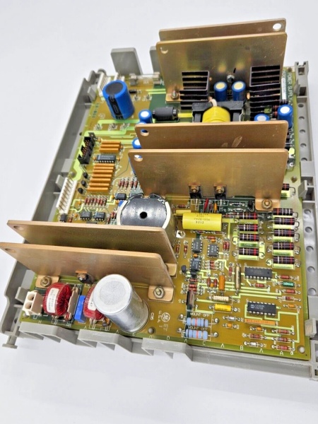
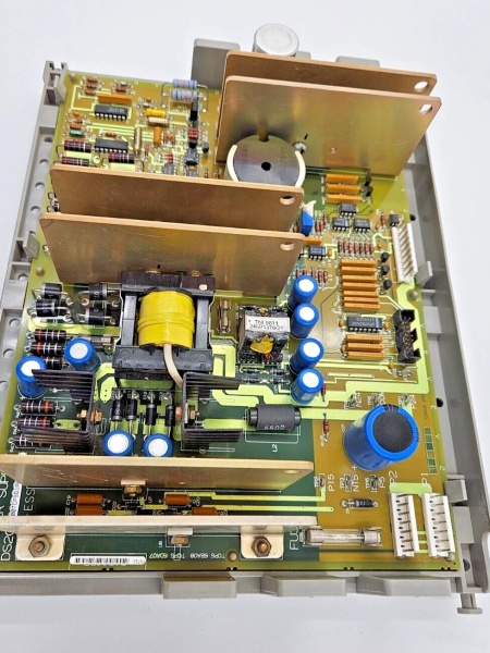
GE DS200TCPSG1APE
Field Service Pitfalls: What Rookies Get Wrong
Confusing PE with standard TCPS causes configuration errorsMixing up PE and standard boards. I’ve seen technicians installing standard TCPS where TCPS-PE belongs, losing PE-specific features and causing system incompatibility.
- Field Rule: Clearly identify TCPS-PE vs. standard TCPS. TCPS-PE has PE-specific configuration for particular power distribution requirements. Standard TCPS lacks PE-specific features. Check board label for “PE” suffix. Never assume TCPS boards are identical—PE provides specialized capabilities.
Overlooking PE input power requirements causes failuresApplying incorrect input voltage. I’ve seen technicians applying standard input voltage to PE boards, causing board failure or insufficient capacity.
- Field Rule: Verify PE input power requirements before connection. PE may require specific input voltage ranges or have different input characteristics. Check that input voltage matches PE specification. Verify input polarity is correct. Never assume standard input works—verify PE input requirements first.
Skipping PE-specific output capacity verification causes overload issuesNot checking PE output capacity. I’ve seen technicians overloading PE outputs using standard TCPS ratings, causing overload conditions.
- Field Rule: Verify PE output capacity before load connection. PE may have different output current capacities than standard TCPS. Check that loads do not exceed PE-specific output ratings. Monitor output currents during full load operation. Never assume standard ratings apply—use PE-specific capacity ratings.
Neglecting PE-specific voltage regulation characteristics causes stability issuesNot understanding PE regulation features. I’ve seen technicians expecting standard regulation from PE boards, causing unexpected voltage behavior.
- Field Rule: Learn PE voltage regulation characteristics. PE may use specialized regulation circuits or have different tolerance specifications. PE may have enhanced regulation features or response characteristics. Check PE-specific regulation documentation. Never assume PE uses standard regulation—learn PE-specific regulation features.
Forgetting to verify PE power sequencing causes startup issuesNot checking PE sequencing. I’ve seen technicians installing PE boards without verifying PE-specific sequencing, causing startup failures.
- Field Rule: Verify PE power sequencing after PE installation. PE may use specialized sequencing order or timing. Check that output voltages sequence correctly according to PE specifications. Test sequencing during cold starts and restarts. Never assume standard sequencing applies—verify PE-specific sequencing before placing in service.
Overlooking PE diagnostic enhancements causes missed faultsNot utilizing PE diagnostic features. I’ve seen technicians installing PE boards but not understanding PE-specific diagnostic capabilities, missing fault information.
- Field Rule: Learn PE diagnostic enhancements. PE may include specialized diagnostic parameters or fault detection. Use PE-specific diagnostic tools for fault identification. Document PE-specific diagnostic features. Never assume standard diagnostics apply—utilize PE capabilities.
Improper grounding causes noise and erratic operationIncorrect ground connections. I’ve seen technicians grounding TCPS-PE incorrectly, introducing noise or ground loops into control system power.
- Field Rule: Follow proper grounding procedures for TCPS-PE boards. Use designated ground points from Mark V documentation. Verify ground connections are secure and clean. Check ground resistance meets specifications. Never improvise TCPS-PE grounding—improper grounding causes power noise and erratic operation.
Skipping PE output voltage verification causes control issuesNot measuring PE output voltages. I’ve seen technicians assuming PE outputs match standard voltages without verification, discovering voltage differences during operation.
- Field Rule: Verify all PE output voltages after installation. Measure each output voltage (+5 V, +15 V, -15 V, +24 V) with a calibrated multimeter. Check that voltages match PE specifications. Verify voltages under full load conditions. Never assume outputs are standard—measure all PE voltages before placing in service.
Forgetting to check PE transient protection causes component damageNot verifying PE transient protection features. I’ve seen technicians assuming standard transient protection from PE boards, allowing damage from transients.
- Field Rule: Verify PE transient protection capabilities. PE may include enhanced transient protection or different protection characteristics. Check that PE protection circuits are functional. Ensure external power source compatibility with PE protection. Never assume standard protection applies—verify PE protection features.
Overheating due to PE-specific thermal requirements causes failuresNot providing adequate cooling for PE boards. I’ve seen technicians installing PE boards with standard cooling assumptions, causing thermal issues.
- Field Rule: Ensure adequate cooling for TCPS-PE boards. PE may have different thermal characteristics than standard TCPS. Verify cabinet ventilation provides sufficient airflow for PE thermal requirements. Check board temperature during full load operation. Never use standard cooling assumptions—verify PE thermal requirements.
Commercial Availability & Pricing Note
Please note: The listed price is for reference only and is not binding. Final pricing and terms are subject to negotiation based on current market conditions and availability. As a PE-configured specialized power supply component, availability may be limited and lead times extended. TCPS-PE boards require compatibility verification with input power sources, output load requirements, and PE-specific configurations. Proper application sizing is essential for reliable operation.

