
Description
Key Technical Specifications
-
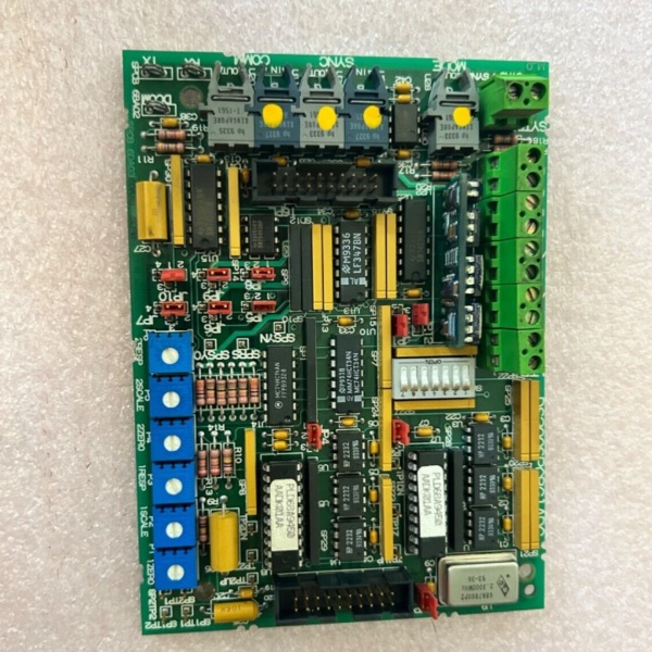
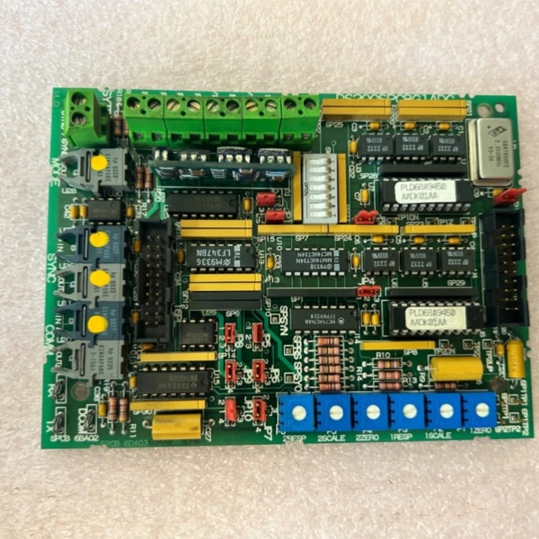
Model Number: DS200SPCBG1A
-
Manufacturer: General Electric
-
Power Requirements: +5 Vdc @ 6 A (logic), +28 Vdc (field)
-
Operating Temperature: –30 °C to +65 °C
-
Connectors: 27 bayonet-type firing outputs, 34-pin & 9-pin D-Sub I/O, fiber ST ports for encoder & bridge-bridge comms
-
Signal Types: Encoder differential TTL, ±10 V analog process control, 820 nm fiber gate pulses
-
Isolation: 1500 Vdc channel-to-ground; 2.5 kV optical on fibers
-
Functions:
– Sends encoder feedback to SDCC
– Converts 4–20 mA / ±10 V process signals to 5 V TTL for SDCC
– Fiber-optic transmit/receive for bridge-to-bridge sync & master-master systems -
Manual: GEI-100172A
-
Board Size: ≈ 11 × 8 in (279 × 203 mm)
-
Weight: 0.25 lbs (≈ 0.11 kg)
-
Repairability: Non-repairable epoxy-sealed traces; replace complete board on failure

DS200SPCBG1A
Field Application & Problem Solved
In a multi-bridge DC2000 stack you have two SCR bridges feeding a common motor. The SDCC only has one set of encoder inputs and one fiber port—this card becomes the traffic cop. It takes the motor encoder on the front end, duplicates the signal, and ships it down fiber to both bridges so they stay in perfect phase. At the same time it scales the 4–20 mA armature-current feedback to 5 V TTL the SDCC A/D can swallow. When a lightning hit blows a fiber receiver you lose one bridge, swap the card in five minutes, and you’re back to full power—no re-cal, no download. Bottom line: no SPCB, no synchronized bridges; no sync, no regenerative braking.
In a multi-bridge DC2000 stack you have two SCR bridges feeding a common motor. The SDCC only has one set of encoder inputs and one fiber port—this card becomes the traffic cop. It takes the motor encoder on the front end, duplicates the signal, and ships it down fiber to both bridges so they stay in perfect phase. At the same time it scales the 4–20 mA armature-current feedback to 5 V TTL the SDCC A/D can swallow. When a lightning hit blows a fiber receiver you lose one bridge, swap the card in five minutes, and you’re back to full power—no re-cal, no download. Bottom line: no SPCB, no synchronized bridges; no sync, no regenerative braking.
Installation & Maintenance Pitfalls (Expert Tips)
Fiber bend radius is 1.5 in—no exceptions
Sharp kinks add 3 dB loss; the bridge sees 8 mA instead of 15 and misfires. Use the orange plastic guide riveted to the bulkhead and zip-tie every 6 in.
Fiber bend radius is 1.5 in—no exceptions
Sharp kinks add 3 dB loss; the bridge sees 8 mA instead of 15 and misfires. Use the orange plastic guide riveted to the bulkhead and zip-tie every 6 in.
Bayonet outputs must click twice
These carry 15 V gate at 3 A peak. A half-latch adds 2 Ω resistance; the SCR sees 12 mA instead of 150 and misfires. Twist until you feel the second detent, then tug-test.
These carry 15 V gate at 3 A peak. A half-latch adds 2 Ω resistance; the SCR sees 12 mA instead of 150 and misfires. Twist until you feel the second detent, then tug-test.
DS200SPCBG1A
28 V field supply is NOT optional
The board derives its gate drivers from 28 V. If your battery charger is set to 24 V the DC-DC folds back and you’ll chase intermittent “GATE UNDER-V.” Meter the Mate-N-Lock at 28 V ±2 % before you close the cabinet.
The board derives its gate drivers from 28 V. If your battery charger is set to 24 V the DC-DC folds back and you’ll chase intermittent “GATE UNDER-V.” Meter the Mate-N-Lock at 28 V ±2 % before you close the cabinet.
Non-repairable means exactly that
Epoxy-potted traces won’t take a solder iron. If a bayonet pad lifts, order a new board—attempting repair voids the UL listing and you’ll fight the same fault next month
Epoxy-potted traces won’t take a solder iron. If a bayonet pad lifts, order a new board—attempting repair voids the UL listing and you’ll fight the same fault next month
.


