
Description
Hard-Numbers: Technical Specifications
- Functional Acronym: PCCA
- Group Number: G62 (indicates specific voltage/power configuration)
- Voltage Rating: Determined by G62 group classification
- Power Conversion Type: Regenerative or non-regenerative (depends on G62 group spec)
- Connectors: 12 plug connectors (1RPL-6RPL, 1FPL-6FPL for gate pulses, 5PL for power supply communication)
- Configuration Jumpers: 4 wire jumpers (JP1, JP2, WP3, WP4)
- Pulse Transformers: Multiple onboard for gate drive isolation
- Protection: Leg fuses and reactors (G62 group typically uses leg fuses)
- PCB Coating: Normal coating (non-conformal)
- Mounting: Secured to board carrier via plastic holders
- Dimensions: Standard Mark V PCCA form factor
- Manual: GEI-100161 (PCCA Power Connect Card Manual)
- Revisions: Functional Revision A, Functional Revision 2, Artwork Revision B

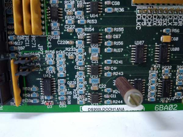
GE DS200LDCCH1ANA
The Real-World Problem It Solves
High-horsepower drive systems require robust power interfaces between low-voltage control electronics and high-power SCR bridges. The DS200PCCA62ACB provides the critical gate drive signal isolation and distribution needed to fire SCRs reliably in demanding industrial environments. Its G62 group classification tailors it for specific voltage and power conversion requirements found in large motor and turbine applications.
Where you’ll typically find it:
- High-horsepower DC motor drives in steel mills
- Turbine excitation systems in power generation
- Large compressor and pump drives
- Regenerative drive systems requiring bidirectional power flow
Bottom line: High-reliability power interface for SCR gate control in demanding drive applications.
Hardware Architecture & Under-the-Hood Logic
The DS200PCCA62ACB serves as the interface between the drive control circuitry and the SCR power bridge, transmitting gate drive pulses through pulse transformers for isolation. This Group 62 variant contains specific hardware configurations tailored to its voltage and power conversion type. The board includes leg fuses and reactors for protection, and uses multiple plug connectors to distribute gate pulses to individual SCR devices in the bridge. Four configurable jumpers allow site-specific adjustments to capacitor connections and voltage feedback circuitry. The board lacks onboard diagnostic components like LEDs or test points, relying on system-level diagnostics for fault detection.
Signal flow:
- Gate drive control signals received from drive control board
- Signals routed through pulse transformers for galvanic isolation
- Isolated gate pulses transmitted via 1FPL-6FPL connectors to forward SCR bridge
- Reverse gate pulses transmitted via 1RPL-6RPL connectors for regenerative operation
- Power supply communication handled through 5PL connector
- Leg fuses provide overcurrent protection for each SCR phase leg
- Reactors limit di/dt and smooth current flow
- Jumpers JP1 and JP2 configure system voltage and stab terminal connections
- Jumpers WP3 and WP4 configure snubber capacitor connections relative to voltage feedback
- Voltage feedback signals monitored for bridge status
- No onboard diagnostics—fault detection through system-level monitoring
- Board mounted on board carrier behind drive control board
GE DS200LDCCH1ANA
Field Service Pitfalls: What Rookies Get Wrong
Mismatching jumper settings during replacement causes configuration errorsWrong JP1/JP2/WP3/WP4 positions. I’ve seen technicians installing replacement boards without copying the jumper configuration from the original, resulting in incorrect voltage settings and snubber connections.
- Field Rule: Photograph all jumper positions on the failed board before removal. The G62 group requires specific jumper settings for your system voltage and snubber configuration. JP1 and JP2 connect to stab terminals P3-P10 and select system voltage. WP3 and WP4 configure snubber capacitor connections to voltage feedback. Never assume factory defaults match your installation. Document all four jumper positions with their identifiers.
Reversing forward/reverse plug connectors causes SCR firing failuresSwapped 1FPL/1RPL connections. I’ve seen technicians connecting the forward gate pulse connectors to the reverse SCR bridge and vice versa, causing firing sequence chaos and potential SCR damage.
- Field Rule: Label all 12 plug connectors clearly during removal with their source and destination. 1FPL through 6FPL connect to the forward SCR bridge. 1RPL through 6RPL connect to the reverse SCR bridge for regenerative operation. Never rely on memory—verify connector routing against system documentation. Test firing sequence after installation using a scope.
Forgetting leg fuse ratings causes immediate failuresWrong fuse values installed. I’ve seen technicians replacing blown leg fuses with incorrect ratings, causing either nuisance tripping or catastrophic SCR failures during overcurrent events.
- Field Rule: Verify the exact fuse rating and type for each leg fuse position. G62 boards typically use leg fuses with specific current and voltage ratings determined by the drive horsepower. Never substitute with different ratings—use only the exact replacement specified in the manual. Document fuse ratings in your maintenance log. Check all leg fuses after any fault event.
Misinterpreting lack of onboard diagnostics as board failureNo LEDs or test points confuse troubleshooting. I’ve seen technicians replacing good boards because they couldn’t diagnose them directly, not realizing PCCA boards rely on system-level diagnostics.
- Field Rule: Use the drive control panel diagnostics to identify PCCA-related faults. The board has no LEDs, test points, or fuses for direct troubleshooting. System diagnostics can identify gate pulse issues, SCR firing problems, and communication faults through the 5PL connector. Never replace a PCCA board without first running system diagnostics to isolate the problem.
Over-tightening plastic holders cracks the PCBExcessive force during mounting. I’ve seen technicians applying too much force when securing the board to the carrier, cracking the PCB and causing intermittent faults.
- Field Rule: Use minimal torque to engage the six plastic holders. The holders should click into place without excessive force. If resistance is felt, verify the board is properly aligned before applying more pressure. Never use pliers or tools to force the holders. Inspect the PCB for stress cracks after installation.
Ignoring reactor connections causes current spikesLoose reactor terminations. I’ve seen technicians failing to properly torque the leg reactor connections, causing di/dt issues and current spikes that stress the SCRs.
- Field Rule: Verify all reactor connections are tight and properly torqued to specification. Reactors limit current rise time and protect SCRs during switching events. Use a torque screwdriver for terminal connections. Check for signs of overheating on reactor windings. Never operate with loose reactor connections—this can cause immediate SCR damage.
Assuming G62 interchangeability with other groups causes system mismatchWrong group substitution. I’ve seen technicians using a G62 board to replace a different group PCCA, resulting in voltage and configuration incompatibilities.
- Field Rule: Match the exact group number when replacing PCCA boards. The G62 designation indicates specific voltage, power conversion type, and hardware configuration that differs from other groups. Cross-reference the system requirements with the board group number. Never assume group interchangeability—verify the complete part number including the group designation.
Dropping screws into the cabinet during replacement creates shortsHardware falls into live cabinet. I’ve seen technicians dropping mounting screws during installation, where they can create short circuits or become lodged in cooling fans.
- Field Rule: Use a magnetic screwdriver or retain screws with your free hand when removing the board. Cover any openings in the cabinet with a cloth during replacement to catch dropped hardware. Never leave loose hardware in the cabinet after installation. Count screws before and after the job to ensure none are missing.
Commercial Availability & Pricing Note
Please note: The listed price is for reference only and is not binding. Final pricing and terms are subject to negotiation based on current market conditions and availability.


