
Description
Hard-Numbers: Technical Specifications
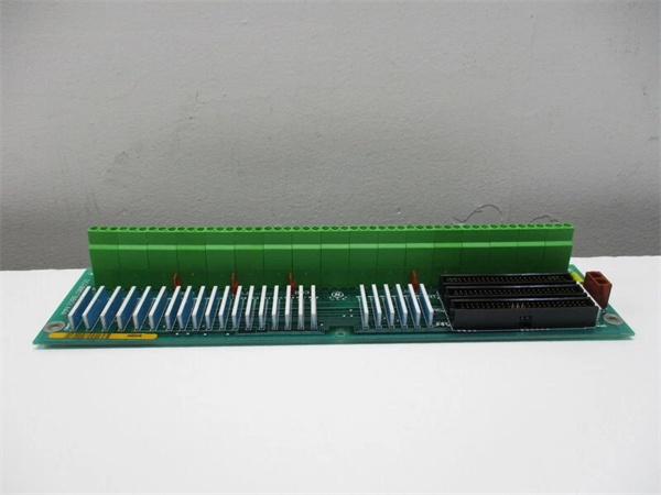
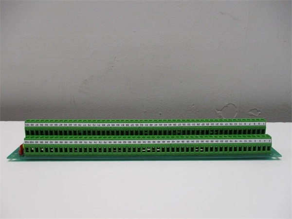
- Terminal Blocks: 2 (TB1, TB2)
- Wires per Block: 95 maximum
- Total Wire Capacity: 190 wires
- Input Voltage Range: 24 VDC to 125 VDC
- Jumpers: 5 configurable jumpers for isolation testing
- Connectors: JFF, JFG, JFH (50-pin ribbon cable connectors)
- Contact Inputs Supported: 47-96 (50 contacts)
- External Power Required: Yes for 24 VDC applications
- Optical Isolation: Each input optically isolated on TCDA board
- Timestamp Resolution: 1 millisecond for contact state changes
- PCB Coating: Normal conformal coating
- Operating Temperature: -40°C to +85°C
- Dimensions: 28.8 cm × 7.2 cm × 3.5 cm
- Weight: 0.36 kg
- Mounting: Rack-mounted in drive cabinet

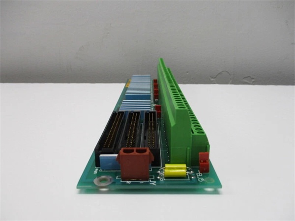
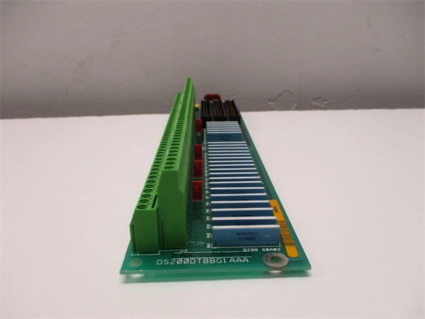
GE DS200DTBBG1AAA
The Real-World Problem It Solves
Digital contact inputs 47-96 need organized termination with configurable excitation voltage. The DS200DTBBG1AAA provides high-density termination for the second bank of contacts in Mark V systems, supporting both 24 VDC and 125 VDC interrogation voltages and routing signals to the TCDA expansion input channels via 50-pin ribbon cables.
Where you’ll typically find it:
- GE Mark V turbine control panels requiring expanded digital input capacity
- Systems where DTBA handles inputs 1-46 and DTBB handles inputs 47-96
- Gas and steam turbine digital input expansion racks
- Field device termination for the second contact input bank (auxiliary limit switches, status contacts, interlocks)
Bottom line: Expansion terminal board for digital contact inputs 47-96 with configurable voltage and optical isolation.
Hardware Architecture & Under-the-Hood Logic
The DS200DTBBG1AAA serves as the termination point for digital contact inputs 47-96 in the Mark V system. It complements the DTBA board (inputs 1-46) by providing termination for the second 50-contact bank. Field devices connect to the two terminal blocks, and signals are routed to the TCDA expansion board via three 50-pin ribbon cable connectors (JFF, JFG, JFH). The board supports both 24 VDC and 125 VDC interrogation voltage from the power distribution core. Jumpers allow isolation of contact outputs for testing.
Signal flow:
- Field devices wired to TB1 and TB2 terminal blocks (up to 190 wires)
- For 24 VDC applications, external power supply connected to terminal board
- Contact signals routed through terminal blocks to internal circuitry
- Jumpers configured for normal operation or test isolation mode
- Conditioned contact signals transmitted via ribbon cables through JFF, JFG, JFH connectors
- Ribbon cables connect to TCDA expansion board channels 47-96
- TCDA board provides optical isolation for each contact input
- CPU on TCDA board assigns 1-millisecond timestamp to state changes
- Diagnostic information transmitted to main control processor
- Input status monitored in synchronization with DTBA inputs 1-46
GE DS200DTBBG1AAA
Field Service Pitfalls: What Rookies Get Wrong
Swapping ribbon cables JFF, JFG, and JFH causes input mapping errorsThree ribbon cables look identical. I’ve seen technicians reinstalling ribbon cables in random order, causing inputs 47-96 to misalign and triggering false logic.
- Field Rule: Label each ribbon cable with connector ID before removal. Mark cables as “JFF-TCDA”, “JFG-TCDA”, “JFH-TCDA” using heat-shrink markers. Document which ribbon cable connects to which TCDA connector position. Never assume ribbon cables are interchangeable—they route specific input groups. Create a wiring diagram showing ribbon cable orientation. Verify input mapping after replacement using the operator interface.
Miswiring 190 wires without documentation causes chaos during replacementHigh wire density means mistakes are costly. I’ve seen technicians removing all wires without labeling, spending days tracing circuits during recommissioning.
- Field Rule: Document every wire location before removal. Label each wire with terminal block ID and terminal number (e.g., TB1-42, TB2-88). Photograph the terminal blocks with wires attached. If possible, reconnect wires to the new board before installing it in the cabinet. Never rely on memory—190 wires will not fit in your head. Create a wiring diagram and verify against original documentation.
Forgetting external power for 24 VDC inputs causes non-responsive contacts24 VDC operation requires external supply. I’ve seen technicians replacing DTBB in 24 VDC applications without connecting external power, wondering why all inputs read “open.”
- Field Rule: Verify the interrogation voltage configuration before replacement. If the system uses 24 VDC inputs, the DTBB board requires an external 24 VDC power supply—disconnect power from the distribution core and connect external source. Test terminal voltage before energizing field devices. Document power configuration in your maintenance procedures. Never assume all Mark V systems use 125 VDC interrogation.
Incorrect jumper configuration causes ground loops during testingJumpers isolate contact outputs. I’ve seen technicians leaving all jumpers in default position during fault isolation testing, failing to break ground loops and wasting hours chasing ghosts.
- Field Rule: Understand jumper functions before troubleshooting. DTBB has five jumpers for isolation testing—remove jumpers to cut interrogation voltage to specific input groups. Only change jumpers when the turbine is not in operation. Document jumper positions before modification. Restore jumpers to original position after testing. Never operate with jumpers in test configuration.
Solid-state field contacts cause false “closed” readingsLeakage current fools the input. I’ve seen technicians troubleshooting phantom “closed” inputs on DTBB, not realizing solid-state relays in the field still conduct enough voltage in the “off” state to trigger the input.
- Field Rule: Verify field device type before troubleshooting. Solid-state contacts may present sufficient voltage in “open” state to register as “closed” on DTBB inputs. Check field device specifications for leakage current. If solid-state devices are used, consider adding a shunt resistor or using compatible input modules. Document which inputs use solid-state versus mechanical contacts for future reference.
Over-tightening terminal screws strips threads and breaks wiresExcessive torque damages terminals. I’ve seen technicians using power drivers on terminal screws, stripping threads and causing intermittent connections.
- Field Rule: Use a manual screwdriver only. Torque terminal screws to 8-10 in-lbs. For stranded wire, use ferrules to prevent strand breakout and ensure proper contact. Never use power drivers on terminal blocks. Re-torque after initial heat cycle (24 hours). Document torque values in your maintenance procedures.
Mixing DTBB with DTBA causes input range confusionDTBB handles 47-96, DTBA handles 1-46. I’ve seen technicians confusing the boards during replacement, installing a DTBA where a DTBB belongs, losing inputs 47-96 entirely.
- Field Rule: Verify the correct part number before installation. DTBB = inputs 47-96, DTBA = inputs 1-46. Cross-reference the board label with the input range required in your application. Test inputs 47-96 after replacement to verify correct function. Never assume terminal boards are interchangeable. Document the difference in your site documentation.
Improper cable routing blocks airflow and causes EMI issuesSignal cables draped over components. I’ve seen ribbon cables routed over power supplies and blocking cabinet airflow, causing overheating and 60Hz noise on digital inputs.
- Field Rule: Route ribbon cables through designated cable channels. Maintain minimum 3-inch separation from power cables. Use cable ties to secure cables—do not allow them to dangle freely. Document cable routing in cabinet drawings. Never route signal cables near high-voltage conductors. Ensure airflow is not obstructed by cable bundles.
Hot-swapping wires while energized damages the boardLive wiring causes voltage transients. I’ve seen technicians adding or removing field wires while the board is powered, causing voltage spikes that travel back to the TCDA board and blow optoisolators.
- Field Rule: Follow lockout/tagout procedures before modifying field wiring. De-energize the terminal board and verify zero voltage state. Never hot-swap field wires—even low-voltage signals can induce transients when disconnected under load. Document LOTO procedures. Train all technicians on proper de-energization. Live wiring risks board damage and personnel safety.
Confusing DTBB with DTBD or DTBC causes wrong board installationDTBB = digital input 47-96, DTBD = digital output expansion, DTBC = contact output. I’ve seen technicians ordering the wrong board because part numbers look similar.
- Field Rule: Memorize the naming convention. DTBB = Contact Input Expansion Termination (inputs 47-96). DTBD = Contact Output Expansion Termination (outputs). DTBC = Contact Output Termination. Cross-reference the part number with the board function before ordering. Never guess based on visual similarity alone. Verify the part number against the spare parts list.
Commercial Availability & Pricing Note
Please note: The listed price is for reference only and is not binding. Final pricing and terms are subject to negotiation based on current market conditions and availability.


