
Description
Hard-Numbers: Technical Specifications
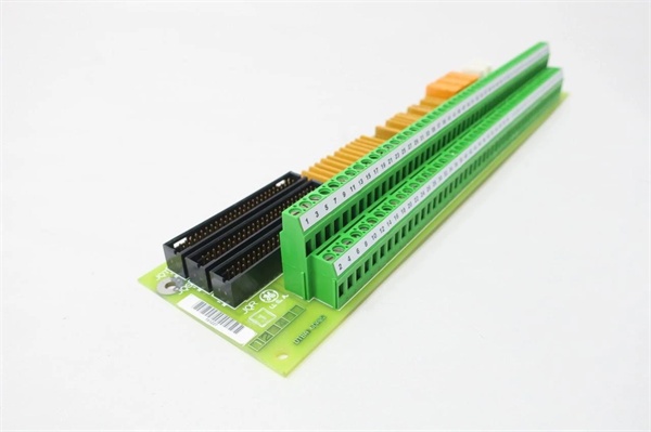
- Terminal Blocks: 2 (TB1, TB2)
- Wires per Block: 95 maximum
- Total Wire Capacity: 190 wires
- Input Voltage Range: 24 VDC to 125 VDC
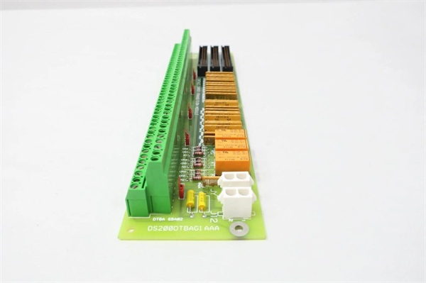
- Jumpers: 5 (BJ1-BJ5 for contact isolation testing)
- Connectors: 4 (JQR, J12, JQS/T, JY)
- 2-Pin Connectors: 2 for power and communications
- Contact Inputs: 46 digital inputs (DTBA handles inputs 1-46)
- Excitation Voltage: 125 VDC from core or 24 VDC from core (factory-configured)
- Optical Isolation: Each input optically isolated on TCDA board
- Timestamp Resolution: 1 millisecond for contact state changes
- PCB Coating: Normal conformal coating
- Operating Temperature: -40°C to +85°C
- Dimensions: 28.8 cm × 7.2 cm × 3.5 cm
- Weight: 0.36 kg
- Mounting: Rack-mounted in drive cabinet

GE DS200DTBAG1AAA
The Real-World Problem It Solves
Digital contact inputs from field devices need organized termination with configurable excitation voltage and fail-safe functionality. The DS200DTBAG1AAA provides high-density termination for up to 46 contacts, supporting both 24 VDC and 125 VDC interrogation voltages with isolation for field ground protection.
Where you’ll typically find it:
- GE Mark V LM turbine control panels
- Gas and steam turbine digital input racks
- Contact input termination for TCDA boards in digital cores
- Field device termination (limit switches, pressure switches, relay contacts)
Bottom line: High-density digital contact termination with configurable voltage and optical isolation for Mark V systems.
Hardware Architecture & Under-the-Hood Logic
The DS200DTBAG1AAA serves as the termination point for digital contact inputs 1-46 in the Mark V LM system. Field devices connect to the two terminal blocks, which route signals to the TCDA board via the JQR connector. The board receives interrogation voltage (125 VDC or 24 VDC) from the power distribution core via the JY connector. Jumpers BJ1-BJ5 allow isolation of contact outputs for testing purposes, enabling field ground isolation by cutting off interrogation voltage to specific input groups.
Signal flow:
- Field devices wired to TB1 and TB2 terminal blocks (up to 190 wires)
- Interrogation voltage (125 VDC or 24 VDC) supplied via JY connector from power core
- Contact signals routed through terminal blocks to internal circuitry
- Jumpers BJ1-BJ5 configured for normal operation or test isolation mode
- Conditioned contact signals transmitted to TCDA board via JQR connector
- TCDA board provides optical isolation for each contact input
- CPU on TCDA board assigns 1-millisecond timestamp to state changes
- Optional diagnostic logging records timestamped events to operator interface
- J12 connector provides 125 VDC power distribution
- JQS/T connector available but rarely used in typical applications
GE DS200DTBAG1AAA
Field Service Pitfalls: What Rookies Get Wrong
Miswiring 190 wires without documentation causes chaos during replacementHigh wire density means mistakes are costly. I’ve seen technicians removing all wires without labeling, spending days tracing circuits during recommissioning.
- Field Rule: Document every wire location before removal. Label each wire with terminal block ID and terminal number (e.g., TB1-45, TB2-88). Photograph the terminal blocks with wires attached. If possible, reconnect wires to the new board before installing it in the cabinet. Never rely on memory—190 wires will not fit in your head. Create a wiring diagram and verify against original documentation.
Over-tightening terminal screws strips threads and breaks wiresExcessive torque damages terminals. I’ve seen technicians using power drivers on terminal screws, stripping threads and causing intermittent connections.
- Field Rule: Use a manual screwdriver only. Torque terminal screws to manufacturer specification—typically 8-10 in-lbs for this terminal type. For stranded wire, use ferrules to prevent strand breakout and ensure proper contact. Never use power drivers on terminal blocks. Re-torque after initial heat cycle (24 hours). Document torque values in your maintenance procedures.
Ignoring jumper configuration causes ground loops during testingJumpers isolate contact outputs. I’ve seen technicians leaving all jumpers in default position during fault isolation testing, failing to break ground loops and wasting hours chasing ghosts.
- Field Rule: Understand jumper functions before troubleshooting. BJ1-BJ5 isolate contact outputs for testing—remove jumpers to cut interrogation voltage to specific input groups. Only change jumpers when the turbine is not in operation. Document jumper positions before modification. Restore jumpers to original position after testing. Never operate with jumpers in test configuration.
Applying 125 VDC to 24 VDC configured inputs damages field devicesVoltage configuration is factory-set. I’ve seen technicians assuming all inputs accept 125 VDC, applying high voltage to 24 VDC-rated field devices and destroying them.
- Field Rule: Verify excitation voltage configuration before wiring field devices. The TB2 terminal board allows 125 VDC from core or 24 VDC from core—implementation is factory-configured. Check the manual for your specific configuration. Test voltage at terminals before connecting field devices. Use a multimeter to verify 24 VDC or 125 VDC as expected. Never guess—wrong voltage kills equipment.
Solid-state field contacts cause false “closed” readingsLeakage current fools the input. I’ve seen technicians troubleshooting phantom “closed” inputs, not realizing solid-state relays in the field still conduct enough voltage in the “off” state to trigger the input.
- Field Rule: Verify field device type before troubleshooting. Solid-state contacts may present sufficient voltage in “open” state to register as “closed” on DTBA inputs. Check field device specifications for leakage current. If solid-state devices are used, consider adding a shunt resistor or using compatible input modules. Document which inputs use solid-state versus mechanical contacts for future reference.
Mixing signal and power cables causes noise and intermittent faultsEMI corrupts digital inputs. I’ve seen technicians routing signal wires alongside 480 VAC power cables, causing erratic input behavior and nuisance trips.
- Field Rule: Maintain minimum separation between signal and power cables—12 inches recommended, 6 inches absolute minimum. Use shielded cable for long runs (>50 feet). Ground shields at the cabinet end only. Never bundle signal cables with power cables in the same conduit. Route signal cables through separate cable trays. Document cable routing—proper separation prevents 90% of noise problems.
Removing wires with screwdriver slips causes short circuitsScrewdriver hits adjacent terminals. I’ve seen technicians removing wires in a cramped cabinet, the screwdriver slipping and shorting adjacent terminals, blowing fuses and damaging the TCDA board.
- Field Rule: Use one hand to guide the screwdriver, the other to turn. Maintain good line of sight—use a flashlight if needed. If possible, de-energize the board before removing wires. If power must remain on, use insulated screwdrivers. Move wires to the side as you remove them—keep them clear of the work area. Never work in a cramped space without adequate lighting and clearance.
Forgetting ESD protection damages optoisolators on TCDA boardStatic kills isolation circuits. I’ve seen technicians handling the DTBA board without grounding, then plugging it into the system and blowing optoisolators on the TCDA board.
- Field Rule: Always ground yourself before handling any board. Use an anti-static wrist strap connected to cabinet ground. Hold the board by the edges only—never touch components. Store the board in anti-static packaging when not installed. Ground the cabinet before board installation. Never place the board on conductive surfaces. ESD damage may not show immediately but causes premature failure.
Confusing DTBA with DTBB causes input mapping errorsDTBA handles inputs 1-46, DTBB handles 47-96. I’ve seen technicians replacing DTBA with a DTBB board, wondering why inputs 47-96 work but 1-46 are dead.
- Field Rule: Verify the correct part number before installation. DTBA = inputs 1-46, DTBB = inputs 47-96. Cross-reference the board label with the input range required in your application. Test inputs after replacement—verify inputs 1-46 respond correctly. Never assume terminal boards are interchangeable. Document the difference in your site documentation.
Improper terminal block torque causes thermal runawayLoose connections heat up. I’ve seen technicians undertorquing terminal screws, causing high-resistance connections that overheat and melt insulation, leading to short circuits.
- Field Rule: Use a calibrated torque wrench for critical applications. Torque to manufacturer specification—typically 8-10 in-lbs. For high-current applications, use a torque screwdriver for precision. Re-torque after initial heat cycle (24 hours) and annually thereafter. Inspect terminals for discoloration—indicates overheating. Document torque values and schedule. Never ignore warm terminals—heat equals resistance equals failure.
Hot-swapping wires while energized damages the boardLive wiring causes voltage transients. I’ve seen technicians adding or removing field wires while the board is powered, causing voltage spikes that travel back to the TCDA board and blow optoisolators.
- Field Rule: Follow lockout/tagout procedures before modifying field wiring. De-energize the terminal board and verify zero voltage state. Never hot-swap field wires—even low-voltage signals can induce transients when disconnected under load. Document LOTO procedures. Train all technicians on proper de-energization. Live wiring risks board damage and personnel safety.
Commercial Availability & Pricing Note
Please note: The listed price is for reference only and is not binding. Final pricing and terms are subject to negotiation based on current market conditions and availability.

