
Description
Hard-Numbers: Technical Specifications
- Feedback Inputs: 4 tachometer inputs (AC/DC tach), 5 current transformer (CT) inputs
- Line Commutation: 6 input channels for thyristor bridge monitoring
- Tachometer Input Range: 0-100 VAC (typical), 0-200 VDC (DC tach optional)
- CT Input Range: 0-5 A secondary, compatible with standard 5A CTs
- Output Signals: Digital feedback to drive controller via backplane, 2x 4-20 mA analog outputs
- Isolation: Channel-to-channel 1500V RMS, backplane isolation 500V RMS
- Sampling Rate: 5 kHz per channel, 10 kHz for line commutation (enhanced)
- Accuracy: ±0.05% of reading (speed), ±0.3% of reading (current)
- Backplane Interface: VME-style 96-pin DIN connector
- Power Requirements: +5 VDC @ 4.0 A, +15 VDC @ 1.5 A (higher due to commutation features)
- Operating Temperature: 0°C to 55°C (32°F to 131°F)
- LED Indicators: Power, Tachometer Status (4), CT Status (5), Line Commutation Status (6), Fault
- Diagnostic Capabilities: Enhanced on-board diagnostics, cross-channel monitoring, commutation fault detection
- Terminal Block: Removable screw terminal for field wiring

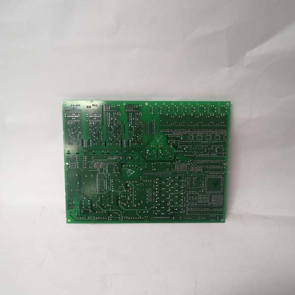
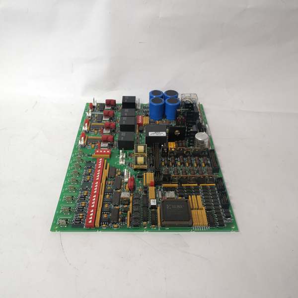
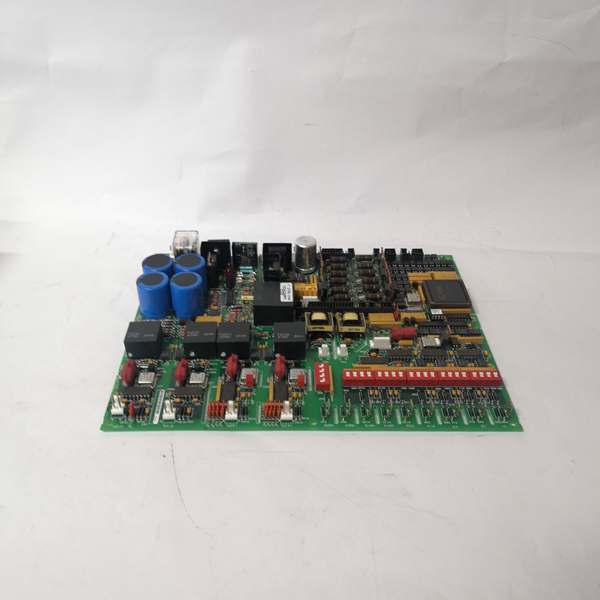
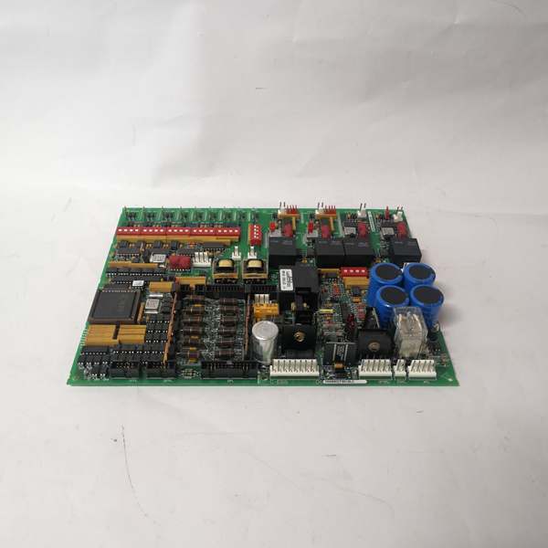
GE DS200DCFBG1BLC
The Real-World Problem It Solves
Regenerative drive applications require coordinated feedback and line commutation. The DS200DCFBG1BLC provides enhanced feedback with integrated line commutation, enabling precise regenerative braking control.
Where you’ll typically find it:
- GE DC regenerative drive systems
- Crane and hoist drive controls
- Turbine start-up and coast-down systems
- Applications with regenerative braking requirements
Bottom line: Enhanced feedback with integrated line commutation for regenerative drives.
Hardware Architecture & Under-the-Hood Logic
The DS200DCFBG1BLC builds on B revision design with integrated line commutation. Four tachometer inputs, five CT inputs, and six line commutation inputs provide comprehensive feedback. Enhanced sampling rate (5 kHz for feedback, 10 kHz for commutation) improves resolution for precision applications.
Signal flow:
- Up to 4 tachometer inputs received (AC or DC tach)
- Tach signals conditioned and filtered
- ADC converts tach signals to digital speed values (5 kHz sampling)
- Up to 5 CT secondary currents converted to voltage via shunts
- CT voltages digitized via ADC (5 kHz sampling)
- Six line commutation inputs monitored for thyristor firing angles (10 kHz)
- Microcontroller processes all feedback and commutation data
- Digital feedback transmitted to drive controller via backplane
- Line commutation timing signals coordinated with drive controller
- Dual 4-20 mA outputs generated for external monitoring
GE DS200DCFBG1BLC
Field Service Pitfalls: What Rookies Get Wrong
Line commutation phase sequence incorrect causes regenerative faultsPhase sequence is critical for regenerative braking. I’ve seen technicians wiring the six commutation inputs out of phase sequence, causing regenerative faults and drive trips.
- Field Rule: Verify phase sequence (L1-L2-L3) before wiring to the six commutation inputs. Use a phase sequence meter to confirm. The commutation inputs must match the thyristor bridge firing sequence. Test regenerative operation by running the motor in reverse torque mode—should regenerate smoothly. Document phase sequence and test results. Reverse any two phases if regenerative faults occur.
Tachometer to CT synchronization causes timing errorsEnhanced synchronization between tach and CT. I’ve seen technicians configuring tach feedback on Channel 1 but CT feedback on Channel 3, causing controller timing errors in regenerative mode.
- Field Rule: Configure tachometer and CT inputs on corresponding channels for each motor (e.g., Motor 1: Tach Ch1 + CT Ch1). Use software tools to verify channel mapping. Test regenerative braking by applying reverse torque—controller should smoothly transition from motoring to regenerating. Document channel synchronization and test results.
Line commutation filtering mismatch causes instabilityCommutation signals require precise filtering. I’ve seen technicians using 50 Hz filtering on 10 kHz commutation inputs, causing erratic firing and drive instability.
- Field Rule: Configure commutation input filtering to match the thyristor firing frequency. For 6-pulse bridges, commutation occurs at 6x line frequency (360 Hz for 60 Hz systems). Set filter bandwidth to 500 Hz minimum for 60 Hz, 400 Hz for 50 Hz. Verify filtering configuration via software tool. Document filter settings and test with a scope.
Forgotten to enable regenerative mode causes motoring-only operationRegenerative mode disabled by default. I’ve seen technicians installing the BLC revision board without enabling regenerative features, limiting the drive to motoring-only operation.
- Field Rule: Enable regenerative mode during commissioning. Configure the board for regenerative braking based on your application (coast-down regen, reverse torque regen, etc.). Test regenerative operation by intentionally applying regenerative torque—drive should absorb power and return to line. Document enabled features and test results. The BLC revision’s line commutation requires regenerative mode enabled.
Hot-swapping line commutation wiring causes thyristor damageLive commutation wiring risks firing thyristors incorrectly. I’ve seen technicians disconnecting commutation inputs while the drive is running, causing misfiring and thyristor failure.
- Field Rule: Follow strict lockout/tagout procedures before modifying line commutation wiring. De-energize the entire drive system including the thyristor bridge. Verify zero energy state on all commutation inputs. Never hot-swap commutation wiring—incorrect wiring while live can fire thyristors randomly. Document LOTO procedures and train all technicians.
Incorrect commutation firing angle calibration causes regenerative spikesFiring angle offset affects regenerative current. I’ve seen technicians failing to calibrate the commutation firing angle, causing current spikes during regenerative braking transitions.
- Field Rule: Calibrate commutation firing angle during commissioning using a calibration routine. Use a current probe on the DC bus to monitor regenerative current—should be smooth during transition. Adjust firing angle offset if spikes or dips occur. Document firing angle calibration and test results. Re-calibrate after any thyristor bridge replacement.
Cross-channel monitoring threshold too tight for regenerative transientsRegenerative operation creates brief feedback discrepancies. I’ve seen technicians setting 2% discrepancy threshold, causing trips during normal regenerative braking transitions.
- Field Rule: Set cross-channel discrepancy threshold higher for regenerative applications. For regenerative drives, 10-15% threshold accommodates normal transients. Test by performing regenerative braking—trip should not occur on normal transitions. Document threshold settings and test results. The BLC revision’s regenerative mode requires higher thresholds.
Overlooking line commutation status LEDs causes missed thyristor faultsSix commutation LEDs provide granular status. I’ve seen technicians ignoring a single flashing “Comm 4 Fault” LED, missing a developing thyristor fault until complete failure.
- Field Rule: Monitor all six line commutation status LEDs during routine inspections. Each LED corresponds to a specific commutation channel—any deviation from normal patterns indicates a problem on that channel. Investigate immediately—thyristor faults can escalate quickly. Document normal LED patterns for all channels. Set up automated alerts if your SCADA system supports reading individual commutation channel health.
CT grounding during regenerative operation causes ground faultsRegenerative currents reverse flow direction. I’ve seen technicians grounding CT secondaries at multiple points during regenerative operation, causing ground fault trips.
- Field Rule: Ground CT secondaries at a single point only—the drive cabinet. Never ground at both the CT location and the cabinet. For regenerative applications, verify grounding scheme accommodates bidirectional current flow. Measure ground potential—should be less than 1 VAC. Document grounding configuration. Use isolated CTs if ground faults persist.
Insufficient power supply causes commutation failuresHigher current draw (4.0A @ 5V) strains supply. I’ve seen technicians replacing the BLC revision board without verifying power supply capacity, causing voltage sag and commutation failures.
- Field Rule: Verify the 5V power supply capacity before installing the BLC revision board. The BLC revision draws 4.0A—ensure supply can handle this load plus other boards. Measure 5V at the board connector under full regenerative load—should be 4.75-5.25V. If voltage sags below 4.75V, upgrade the power supply. Document power supply capacity and voltage measurements.
Commercial Availability & Pricing Note
Please note: The listed price is for reference only and is not binding. Final pricing and terms are subject to negotiation based on current market conditions and availability.


