
Description
Hard-Numbers: Technical Specifications
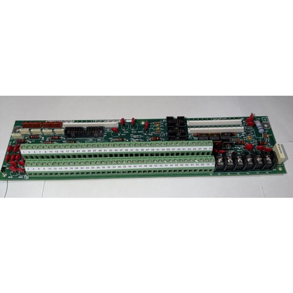
- Terminal Blocks: 24 field terminal blocks (up to 96 terminals total, 4 per block)
- Signal Types: Digital input, Digital output, Analog input, Analog output, Relay output
- Wire Size: 12-22 AWG solid or stranded
- Isolation: Channel-to-channel and channel-to-backplane isolation, 1500V RMS
- Fuse Protection: 24 individual fuse holders (5x20mm, 250V) with status LEDs
- LED Indicators: 24 fuse status LEDs, Power (+5V, +15V, -15V), Board Health
- Backplane Connection: 96-pin ribbon cable to core board
- Current Rating: 5 A per terminal block maximum
- Voltage Rating: 250 VAC/DC maximum
- Power Requirements: +5 VDC @ 1.5 A, +15 VDC @ 0.3 A, -15 VDC @ 0.3 A
- Operating Temperature: 0°C to 55°C (32°F to 131°F)
- Termination Type: Screw terminal with wire guard (cage clamp)
- Diagnostic Capabilities: Fuse status monitoring, continuity checking via backplane
The Real-World Problem It Solves
Field wiring terminates directly to core boards, making maintenance difficult and risking board damage. The DS200CTBAG1ACB provides organized termination with individual fuse protection and status indication.
Where you’ll typically find it:
- GE gas and steam turbine control systems (Mark V)
- Core board I/O termination cabinets
- Protection and control relay interfaces
- Digital and analog signal marshaling
Bottom line: Centralized termination with fuse protection for turbine control I/O.

GE DS200CTBAG1ACB
Hardware Architecture & Under-the-Hood Logic
The DS200CTBAG1ACB serves as the interface between field wiring and core processing boards. Each terminal block connects to a specific channel on the core board via the 96-pin ribbon cable. Individual fuses protect each channel from overcurrent conditions. LEDs provide real-time fuse status indication. The board distributes power (+5V, +15V, -15V) from the backplane to field devices.
Signal flow:
- Field wiring terminated to screw terminals
- Signals pass through individual fuses (5x20mm)
- Protected signals routed to core board via 96-pin ribbon cable
- Core board processes signals and returns output signals
- Output signals routed through output fuses
- Protected output signals sent to field devices via terminals
- Fuse status LEDs indicate blown fuse condition
- Power distribution from backplane to terminals
Field Service Pitfalls: What Rookies Get Wrong
Incorrect fuse rating causes protection failure or nuisance blowsUsing higher-rated fuses defeats protection. I’ve seen technicians replacing blown fuses with 10A fuses in 5A-rated circuits, risking board damage.
- Field Rule: Replace fuses with exact same rating and type (5x20mm, 250V). Never exceed the rated value. Use fast-acting fuses for solid-state outputs, time-delay for inductive loads. Document fuse ratings per terminal block. Maintain a stock of correct fuses. Never bypass fuses—if fuses blow repeatedly, investigate the root cause.
Mixed signal types on same block causes crosstalkDigital noise contaminates analog signals. I’ve seen technicians wiring 4-20 mA analog inputs on the same block as 24 VDC digital outputs, causing erratic readings.
- Field Rule: Separate signal types by terminal block—dedicate blocks for analog inputs, analog outputs, digital inputs, and digital outputs. Follow the terminal block numbering scheme (typically blocks 1-6 for digital, 7-12 for analog, or per board documentation). Document signal type assignments per block. Maintain 1-block minimum separation between sensitive analog and noisy digital signals.
Over-torquing terminal screws strips threadsExcessive torque damages terminals. I’ve seen technicians using power drivers, stripping terminal screws and requiring terminal block replacement.
- Field Rule: Torque terminal screws to 8-10 in-lbs maximum. Use a calibrated torque wrench for critical applications. Never use power drivers. Re-torque after initial heat cycle (24 hours). Document torque values and re-torque schedule. For stranded wire, use wire ferrules to prevent strand breakout and improve torque consistency.
Forgotten to verify wire ferrule causes intermittent connectionsBare stranded wire loosens over time. I’ve seen technicians installing stranded wire without ferrules, causing intermittent connections after thermal cycling.
- Field Rule: Use wire ferrules on all stranded wire (12-22 AWG). Crimp ferrules with the proper tool—never use pliers. Verify ferrule crimp integrity by tugging on the wire. Document ferrule usage guidelines. For solid wire, ferrules are optional but recommended for consistent termination. Never insert bare stranded wire directly into screw terminals.
Ribbon cable misalignment causes pin damage96-pin ribbon cables are not keyed on all boards. I’ve seen technicians offsetting the cable by one pin, blowing core board inputs.
- Field Rule: Verify ribbon cable orientation—Pin 1 typically marked with a red stripe. Align Pin 1 on the cable with Pin 1 on both the terminal board and core board. Use the manufacturer’s pinout diagram. Test I/O operation after installation. Document cable orientation and test results. Never force a ribbon cable—recheck orientation if it doesn’t seat easily.
Incorrect wire gauge causes voltage drop or overheatingSmall wire overheats at high current. I’ve seen technicians using 22 AWG wire on 5A circuits, causing voltage drop and terminal heating.
- Field Rule: Use appropriate wire gauge for the current load. For 5A circuits, use 16-18 AWG minimum. For low-current digital signals (mA range), 20-22 AWG is acceptable. Document wire gauge per terminal block. Calculate voltage drop for long runs—keep below 3%. Never undersize wire to save space or cost.
Ignoring blown fuse LED causes delayed troubleshootingLEDs indicate fuse status. I’ve seen technicians ignoring flashing fuse status LEDs, discovering the problem only after the turbine tripped.
- Field Rule: Monitor fuse status LEDs during routine inspections. Any LED illuminated indicates a blown fuse—investigate immediately. Do not simply replace and restart—identify and correct the root cause (short circuit, ground fault, overload). Document blown fuse events and corrective actions. Replace fuses only after fixing the root cause.
Hot-swapping field wiring while powered damages the boardLive wiring creates ground loops and transients. I’ve seen technicians adding or removing wires while the board is powered, causing blown fuses or damaged inputs.
- Field Rule: Follow proper lockout/tagout procedures before modifying field wiring. De-energize the terminal board and verify zero energy state. Never hot-swap field wires—even low-voltage signals can induce transients. Document LOTO procedures and train all technicians. Live wiring risks board damage and personnel safety.
Improper grounding causes noise and ground loopsMultiple ground references corrupt signals. I’ve seen technicians grounding the shield at both ends, causing ground loops and erratic behavior.
- Field Rule: Ground signal shields at the cabinet end only. For analog signals, use individual shield drain wires per pair. Never ground multiple shields to the same terminal—use separate shield terminals. Verify ground continuity—should be less than 1 ohm. Document grounding configuration. Use shield isolation bars if ground loops persist.
Forgotten to label wires causes confusion and miswiringUnlabeled wires lead to mistakes. I’ve seen technicians relying on wire color conventions, resulting in miswired inputs during maintenance.
- Field Rule: Label both ends of every wire with wire number and function. Use heat-shrink or screw-on wire markers. Follow plant wire numbering scheme. Document the wire number to terminal assignment. Test each wire after installation with a known signal source. Never assume wire color indicates function—always verify with labels and diagrams.
Commercial Availability & Pricing Note
Please note: The listed price is for reference only and is not binding. Final pricing and terms are subject to negotiation based on current market conditions and availability.


