
Description
Hard-Numbers: Technical Specifications
- Pipe Size: 1.5 inches (DN40)
- Flow Range: 1-100 GPM (3.8-380 LPM)
- Accuracy: ±0.5% of reading
- Repeatability: ±0.1% of reading
- Pressure Rating: ANSI 150# (PN16)
- Material: 316 Stainless Steel body, PTFE liner
- Electrode Material: 316 Stainless Steel (Hastelloy C optional)
- Operating Temperature: -20°C to 150°C (-4°F to 302°F)
- Output Signal: 4-20 mA (2-wire loop-powered) with HART
- Fluid Conductivity: Minimum 5 µS/cm (0.05 mS/cm)
- Supply Voltage: 10-35 VDC
- Electrode Count: 2 electrodes (standard) or 4 electrodes (with ground reference)
- Liner Material: PTFE (Teflon) for aggressive chemicals
- Enclosure Rating: NEMA 4X (IP66) polycarbonate
- Minimum Conductivity: 5 µS/cm at 25°C
- Empty Pipe Detection: Yes, configurable alarm

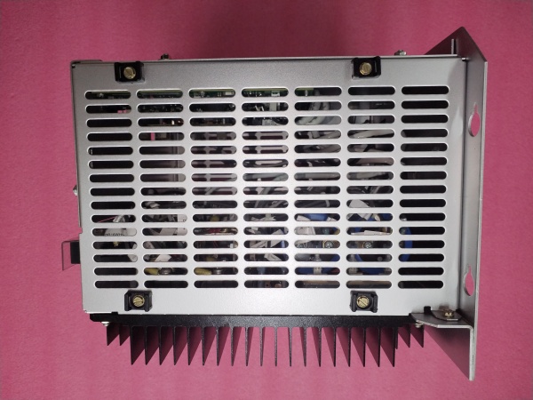
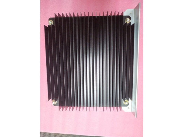
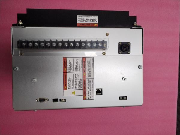
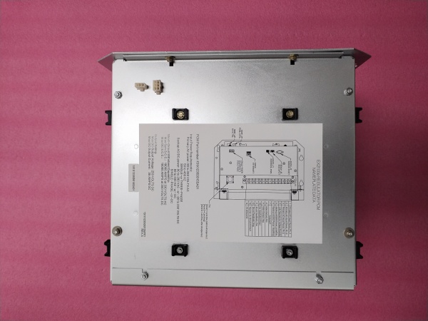
GE 151X1235DB15SA01
The Real-World Problem It Solves
Turbine meters wear out on abrasive fluids; paddle wheels clog on dirty liquids. Magmeters measure flow without obstruction, no moving parts, and negligible pressure drop, ideal for corrosive, abrasive, and conductive fluid applications.
Where you’ll typically find it:
- Acid and caustic chemical transfer lines
- Wastewater treatment and sludge monitoring
- Water distribution and irrigation systems
- Mining slurry and pulp processing
Bottom line: Obstruction-free flow measurement for conductive fluids with no moving parts.
Hardware Architecture & Under-the-Hood Logic
Magmeters operate on Faraday’s Law of Electromagnetic Induction. A magnetic field is generated by coils wound around the flow tube. As conductive fluid flows through the magnetic field, a voltage is induced across the fluid between electrodes. This voltage is directly proportional to flow velocity. The transmitter amplifies and conditions the electrode signal, outputting a 4-20 mA current proportional to flow rate. Empty pipe detection monitors electrode impedance to detect air in the line.
Signal flow:
- Coils generate magnetic field across flow tube
- Conductive fluid flows through magnetic field
- Voltage induced between electrodes proportional to flow velocity
- Electrode signal amplified and conditioned by transmitter
- Signal converted to digital value via ADC
- Transmitter calculates flow rate based on pipe area and voltage
- 4-20 mA output generated proportional to flow rate
- HART communication for configuration and diagnostics
- Empty pipe detection monitors electrode impedance
GE 151X1235DB15SA01
Field Service Pitfalls: What Rookies Get Wrong
Installing in non-conductive fluids causes zero outputMagmeters require conductive fluids. I’ve seen technicians install these in deionized water or hydrocarbon lines, getting zero flow indication regardless of actual flow.
- Field Rule: Verify fluid conductivity exceeds 5 µS/cm at operating temperature before installation. Test fluid conductivity with a portable meter. For low-conductivity fluids (<5 µS/cm), use a turbine, ultrasonic, or Coriolis meter instead. Document fluid conductivity and minimum conductivity requirement in your installation records.
Improper grounding causes signal driftMagmeters require proper grounding to prevent noise pickup. I’ve seen technicians float the meter body, causing erratic readings and zero drift up to 10%.
- Field Rule: Ground the meter body to the same earth ground as the process piping. Use grounding rings if the pipe is plastic or lined. Verify ground continuity with a multimeter—resistance should be less than 1 ohm. Never ground both electrodes to different ground potentials. Document grounding configuration and test results.
Air bubbles cause erratic measurementsEntrained air reduces effective conductivity, causing erratic readings. I’ve seen magmeters oscillate wildly on bubbly lines, triggering false alarms and control actions.
- Field Rule: Install the meter at least 10 pipe diameters downstream of pumps or elbows to allow flow to stabilize. Mount the meter with electrodes at the 3 o’clock and 9 o’clock positions to minimize air bubble impact. Enable empty pipe detection if available. Install an air eliminator upstream if necessary. Test operation—erratic readings indicate air entrainment.
Electrode coating causes measurement driftScaling or fouling on electrodes creates insulation, reducing signal strength. I’ve seen technicians ignore gradual drift, resulting in flow errors up to 5% over months.
- Field Rule: Monitor electrode diagnostic readings via HART. Look for increasing electrode impedance or sensor warnings. Clean electrodes regularly using manufacturer-recommended cleaning procedure (acid wash for scale, mechanical cleaning for fouling). For scaling fluids, consider Hastelloy C electrodes or a magmeter with ultrasonic cleaning. Document cleaning intervals and electrode condition.
Forgotten to compensate for temperatureFluid conductivity changes with temperature. I’ve seen technicians ignore temperature compensation, causing flow errors up to 3% on high-temperature applications.
- Field Rule: Enable temperature compensation in the transmitter configuration. Verify temperature sensor is functioning correctly via HART diagnostics. For applications with wide temperature swings, document temperature vs flow accuracy performance. Consider a Coriolis meter if temperature compensation is insufficient.
Incorrect liner selection for aggressive chemicalsPTFE liners have temperature and pressure limits. I’ve seen technicians install PTFE-lined magmeters on high-temperature acid lines, causing liner failure and leakage.
- Field Rule: Verify liner material (PTFE) compatibility with process fluid at operating temperature and pressure. Check chemical compatibility charts. For high-temperature applications (>150°C), consider PFA or polypropylene liners. Document liner material, fluid, temperature, and pressure compatibility. Replace liner at first signs of degradation or leakage.
Over-torquing flange bolts causes liner deformationPTFE liners can deform if over-tightened. I’ve seen technicians torque bolts to 100 ft-lbs on 150# flanges, causing the liner to compress and distort the flow tube, affecting accuracy.
- Field Rule: Use a calibrated torque wrench and follow the manufacturer’s torque pattern. For 1.5″ 150# flanges, torque to 25-30 ft-lbs in a star pattern. Never exceed the recommended torque. Check for leaks after torquing—if leaks occur, do not over-tighten. Re-seat the gasket and re-torque.
Commercial Availability & Pricing Note
Please note: The listed price is for reference only and is not binding. Final pricing and terms are subject to negotiation based on current market conditions and availability.


