

Description
Hard-Numbers: Technical Specifications
-
Processor Architecture: 32-bit RISC with integrated Floating-Point Unit (FPU)
-
Memory: 8 MB Program / 8 MB Data (expandable via optional memory cards)
-
Backplane Interface: Dual redundant Universal Bus (IABus) – proprietary high-speed peer-to-peer communication
-
Ethernet: 10/100 Mbps for SCADA, HMI, and engineering workstation access
-
Redundancy Support: Hot-standby with automatic failover <100 ms, synchronous operation
-
Operating Temperature: 0°C to 55°C (operating), -40°C to 85°C (storage)
-
Power Draw: Derived from ACP40/A or ACP50 chassis power supply (typically 24V DC backplane)
-
Isolation Rating: Standard industrial isolation per IEC 61000-6-2/6-4
-
Programming Standard: IEC 61131-3 via Foxboro Control Software (FCS) or IA-Tools
- Certifications: CE, UL, CSA, FM, RoHS compliant

The Real-World Problem It Solves
You know the scenario: a single CPU fault in a non-redundant control rack brings down the entire boiler feedwater system or trips the turbine protection logic. The H92904CC0500 eliminates this single point of failure by running dual CPUs in lockstep—both processors execute identical control logic simultaneously, sharing memory state and I/O data across the IABus. When the primary drops, the standby takes over before the process even notices.
Where you’ll typically find it:
-
Thermal and combined-cycle power plants running turbine control and burner management systems
-
Oil refinery process units requiring NFPA 85-compliant flame safeguard logic
-
Offshore platform ESD (Emergency Shutdown) and Fire & Gas systems where remote location makes hardware swaps expensive
Bottom line: It keeps critical control loops alive during CPU hardware failures, planned maintenance, or firmware updates without process interruption.
Hardware Architecture & Under-the-Hood Logic
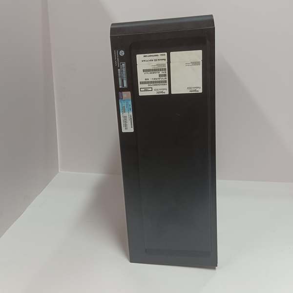
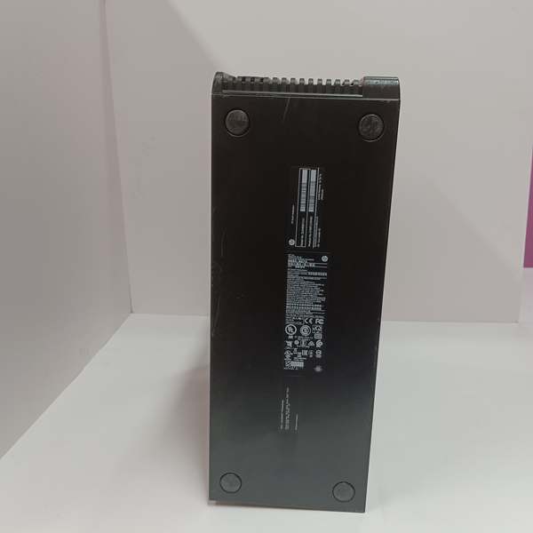
The H92904CC0500 mounts in Slot 1 (primary) and Slot 2 (secondary) of an ACP40/A or ACP50 chassis. Each module contains its own 32-bit RISC microprocessor with FPU for deterministic real-time control. The two CPUs communicate via dedicated high-speed links on the IABus backplane, maintaining bit-for-bit memory synchronization.
Signal flow and processing logic:
-
Input Sampling: Field signals from FBM200-series I/O modules arrive via the IABus backplane to both CPUs simultaneously
-
Lockstep Execution: Both processors run the same control algorithms (PID, cascade, sequential logic) in perfect synchronization, comparing results cycle-by-cycle
-
Output Arbitration: The primary CPU drives the I/O bus while the standby tracks; if divergence exceeds tolerance, failover triggers automatically
-
State Transfer: On failover, the standby assumes control with full knowledge of loop states, setpoints, and alarm conditions—no bumpless transfer required
-
Network Interface: Independent Ethernet ports handle HMI, historian, and engineering traffic without loading the deterministic I/O bus
Field Service Pitfalls: What Rookies Get Wrong
Mismatched Firmware Revisions Installing a primary CPU with firmware v8.4 and a standby with v8.3 causes synchronization faults. The redundancy link will fail to establish, leaving you with two independent processors fighting for I/O control.
Field Rule: Always verify both CPUs show identical firmware versions on the LED display before declaring the redundancy healthy. Flash both units to the latest revision during planned outages.
Improper IABus Termination The H92904CC0500 relies on clean IABus signaling for memory synchronization. Missing termination resistors or loose backplane connectors in the ACP chassis cause intermittent “SYNC LOST” alarms that clear themselves—until they don’t during a critical failover event.
Quick Fix: Inspect the IABus termination jumpers on the chassis backplane whenever swapping CPUs. Check seating force—Foxboro modules require firm pressure until the ejector levers click home. A partially seated module will pass power but fail high-speed bus communication.
Hot-Swapping Without Sync Verification Pulling the primary CPU for replacement before confirming the standby has achieved “SYNC” status drops the entire control strategy. The I/A Series requires explicit operator confirmation of redundancy health before manual switchover.
Field Rule: Never remove the primary H92904CC0500 until the standby shows solid “SYNC” LED (not flashing) and you’ve verified bumpless transfer via the engineering station. Use the “TEST” pushbutton to force a failover first—if it doesn’t switch cleanly, find out why before touching hardware.


