
Description
Hard-Numbers: Technical Specifications
- Series: I/A Series Fieldbus
- Input Channels: 32 (group isolated, 8 per group)
- Input Voltage Range: 24V DC (nominal), 18-32V DC range
- Input Current: 5-7 mA per channel
- Response Time: 10 ms typical (configurable 1-100 ms)
- Filter Time: Configurable 0-255 ms
- Isolation Rating: 1500 VDC group-to-group, 1500 VDC group-to-system
- Wiring Type: 2-wire (sourcing or sinking)
- Power Supply: 24V DC fieldbus power
- Power Draw: 15W typical
- Operating Temperature: -40°C to +70°C
- Storage Temperature: -40°C to +85°C
- Relative Humidity: 5% to 95% non-condensing
- Certifications: CE, UL, CSA, FM, ATEX, IECEx
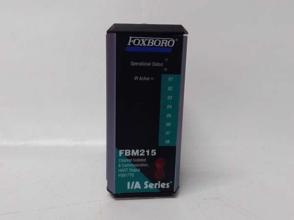
FOXBORO FBM215
The Real-World Problem It Solves
High-density discrete monitoring requires packing many inputs into a limited cabinet footprint. Standard 16-point modules consume excessive space and increase wiring complexity. The FBM216B provides 32 isolated inputs in a compact package, maximizing channel density while maintaining isolation and diagnostic capabilities for reliable discrete status monitoring.
Where you’ll typically find it:
- Motor control centers with multiple motor status inputs
- Batch process systems with numerous limit switches
- Packaging machinery with sensor arrays
- Material handling systems with position indicators
Bottom line: It maximizes channel density while maintaining reliable isolated digital input.
Hardware Architecture & Under-the-Hood Logic
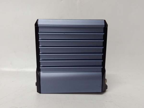
This digital input module contains 32 isolated optocouplers organized in 8-channel groups, configurable input filters, and a microprocessor for signal processing and diagnostics. Groups of 8 channels share isolation barriers, providing protection while optimizing space utilization. The module communicates over the Foxboro fieldbus to the I/A Series control system.
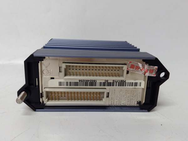
- Field device signals (24V DC) enter through the terminal block and pass through RC input filters.
- Configurable filter circuits suppress contact bounce and voltage transients based on user settings.
- Optocouplers in 8-channel groups provide electrical isolation between field circuits and internal logic.
- Isolated digital signals are digitized by the microprocessor for processing and fieldbus communication.
- Diagnostics circuits monitor input voltage levels, open circuits, short circuits, and wiring faults per channel.
- Watchdog timers monitor microprocessor health, triggering fault alerts if system integrity is compromised.
- Processed input states and diagnostic data are transmitted over the fieldbus to the I/A Series controller.
FOXBORO FBM215
Field Service Pitfalls: What Rookies Get Wrong
Mixed Grounding Within Isolation GroupsRookies connect field devices from different ground potentials within the same 8-channel isolation group. Ground potential differences create circulating currents through optocouplers, causing erratic logic states and false alarms across multiple channels simultaneously.
- Field Rule: Assign field devices with similar ground references to the same isolation group. Use separate groups for devices with different ground potentials. Avoid cross-connection of devices with potential differences exceeding 30V within a single group.
Incorrect Filter Settings on High-Speed InputsNew engineers set uniform filter times across all 32 channels, ignoring differences in device response times. High-speed sensors miss rapid state changes with long filters, while vibrating switches cause false triggers with short filters.
- Quick Fix: Configure filter times per group or per channel based on application. Use 1-5 ms for high-speed pulse counting, 10-20 ms for standard switches, and 50-100 ms for vibrating machinery. Verify response time matches process requirements.
Exceeding Power Budget on 32-Channel ModulesTechnicians don’t account for total current draw when wiring all 32 channels at 5-7 mA each. The module power budget is exceeded, causing voltage drop on the fieldbus and affecting other modules.
- Field Rule: Calculate total current draw: 32 channels × 7 mA = 224 mA maximum. Add this to module base consumption (15W) when sizing the 24V DC fieldbus power supply. Ensure power supply has adequate margin (at least 20% additional capacity).
Poor Wiring Density on High-Count TerminalsRookies wire all 32 channels into tight terminal blocks without considering maintenance access. Testing individual channels becomes a nightmare during troubleshooting, and wire damage occurs from crowding.
- Field Rule: Use properly sized terminal blocks with adequate spacing for 32-channel modules. Label wires clearly at both ends. Leave sufficient slack for individual wire removal. Document channel assignments in the control system database for quick reference.
Please note: The listed price is for reference only and is not binding. Final pricing and terms are subject to negotiation based on current market conditions and availability.


