

Description
Hard-Numbers: Technical Specifications
- Series: I/A Series Fieldbus
- Output Channels: 16 (independent, isolated)
- Output Voltage Range: 24V DC (nominal), 18-30V DC range
- Output Current: 500 mA per channel (max)
- Response Time: 10 ms typical (configurable 1-100 ms)
- Isolation Rating: 1500 VDC channel-to-channel, 1500 VDC channel-to-system
- Output Type: Sourcing (PNP) or sinking (NPN) configurable
- Power Supply: 24V DC fieldbus power
- Power Draw: 12W typical
- Operating Temperature: -40°C to +70°C
- Storage Temperature: -40°C to +85°C
- Relative Humidity: 5% to 95% non-condensing
- Certifications: CE, UL, CSA, FM, ATEX, IECEx
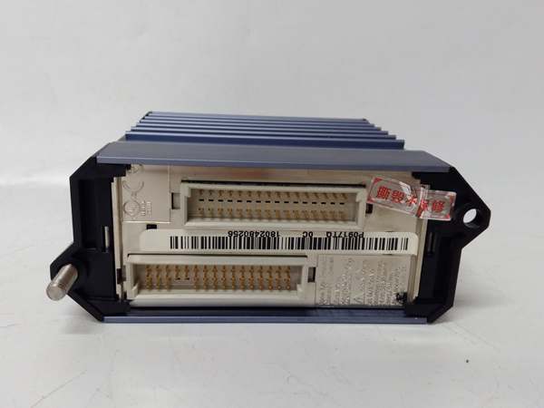
FOXBORO FBM215
The Real-World Problem It Solves
Digital outputs suffer from voltage transients, ground loops, and inductive kickback in industrial environments. Non-isolated output modules let electrical noise and stray currents corrupt output signals, causing unpredictable device operation. The FBM215 provides per-channel isolation eliminating ground loops, configurable output types matching field devices, and digital diagnostics for reliable discrete control across all 16 channels.
Where you’ll typically find it:
- Solenoid valve control in process plants
- Motor starter and contactor control
- Indicator lamp and alarm output
- Actuator and relay drive applications
Bottom line: It delivers reliable, isolated digital output for critical discrete control.
Hardware Architecture & Under-the-Hood Logic
This digital output module contains isolated output drivers, configurable output stages, and a microprocessor for signal processing and diagnostics. Each channel has independent isolation barriers, preventing ground potential differences and voltage transients between field devices from affecting output states. The module communicates over the Foxboro fieldbus to the I/A Series control system.
- The I/A Series controller sends output commands to the FBM215 via the fieldbus.
- The microprocessor validates commands and routes them to appropriate channel processors.
- Isolated output drivers (transistor or relay) activate based on output type configuration (sourcing or sinking).
- Output circuits deliver voltage and current to field devices through terminal connections.
- Diagnostics circuits monitor output current, open circuits, short circuits, and thermal conditions per channel.
- Watchdog timers monitor microprocessor health, triggering fault alerts and driving outputs to safe state on failure.
- Processed output states and diagnostic data are transmitted over the fieldbus to the I/A Series controller.

FOXBORO FBM215
Field Service Pitfalls: What Rookies Get Wrong
Incorrect Output Type ConfigurationRookies configure outputs incorrectly for field device requirements, mixing sourcing (PNP) and sinking (NPN) types. Field devices don’t activate or draw excessive current, causing device failure or erratic operation.
- Field Rule: Verify field device input type (sourcing or sinking) before configuring. Set output type accordingly in I/A Series Configurator. Test each channel individually before putting the system into service.
Exceeding Current Ratings on Inductive LoadsTechnicians connect multiple solenoids or relays to a single output without checking total current. Inductive kickback and excessive current destroy output transistors, requiring module replacement.
- Quick Fix: Calculate total load current per channel, including inrush current. Stay within 500 mA per channel limit. For inductive loads, install external flyback diodes across the coil terminals to protect output transistors from back-EMF.
Ignoring Thermal Derating in High-Temperature CabinetsNew engineers don’t account for cabinet temperature effects on output current ratings. High ambient temperatures reduce current capacity, causing thermal shutdowns or premature output driver failure.
- Field Rule: Derate output current by 50% when cabinet temperature exceeds 50°C. Install forced air cooling to maintain temperature below 45°C. Monitor module temperature using I/A Series diagnostics during initial operation.
Poor Wiring on Multiple Load TypesRookies wire different load types (solenoids, lamps, relays) without considering load characteristics. Mixed loads cause inconsistent response times and voltage drops across channels, leading to unpredictable operation.
- Field Rule: Group similar load types on adjacent channels for consistent performance. Use external relays or contactors for high-current loads to protect module outputs. Verify voltage drop is less than 5% at full load.
Please note: The listed price is for reference only and is not binding. Final pricing and terms are subject to negotiation based on current market conditions and availability.


