
Description
Hard-Numbers: Technical Specifications
- Series: 95 Series
- Scanner Inputs: 4 (UV scanners only)
- Output Relay: 10A at 250V AC (fuel valve safety shutoff)
- Alarm Relay: 5A at 250V AC (fault and status outputs)
- Power Supply: 120/240V AC, 50/60Hz
- Power Draw: 25W typical
- Operating Temperature: -20°C to +60°C
- Storage Temperature: -40°C to +85°C
- Relative Humidity: 5% to 95% non-condensing
- Enclosure: NEMA 4X (IP66) indoor/outdoor rated
- Certifications: UL, FM, CSA, CE, ATEX, IECEx
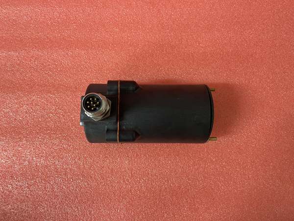
Fireye 85UVF1-1QDK3
The Real-World Problem It Solves
Multi-burner systems need coordinated flame monitoring and safety control across all burners. Multiple single-scanner controllers increase wiring complexity and cost, while reducing diagnostic capability. The 95UVS4-1WINC integrates four UV scanner inputs into a single unit, simplifying installation while providing comprehensive burner management, cross-burner diagnostics, and coordinated safety shutdowns.
Where you’ll typically find it:
- Multi-burner process heaters in refineries
- Power plant boiler combustion systems
- Large industrial ovens and dryers
- Chemical reactor heating systems
Bottom line: It consolidates multi-burner flame monitoring and safety control into one compact unit.
Hardware Architecture & Under-the-Hood Logic
This quad-scanner controller integrates four independent UV scanner input circuits with a microprocessor-based burner management system. The controller executes pre-purge, ignition, and flame monitoring sequences for up to four burners simultaneously. Multiple output relays control fuel valves, dampers, and alarms while providing status feedback to plant DCS or safety systems.
- Four independent UV scanner channels connect via shielded cables, each isolated from the others.
- The microprocessor monitors all four scanner signals simultaneously during burner operation.
- Integrated flame monitoring logic evaluates signal strength, response time, and signal quality per scanner.
- Burner management sequences (pre-purge, ignition, flame stabilization) execute under microprocessor control.
- Main fuel valve relay controls primary fuel supply to all burners with individual burner valve control if required.
- Alarm and status relays provide discrete outputs for flame status, system faults, and interlock states to the control system.
- Watchdog timers monitor microprocessor health, triggering safe shutdown on processor fault or power loss.
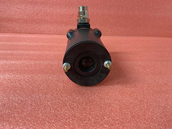
Fireye 85UVF1-1QDK3
Field Service Pitfalls: What Rookies Get Wrong
Mismatched Scanner Wiring Across ChannelsRookies scramble scanner inputs across the four channels, wiring scanners to the wrong controller terminals or mixing up channel assignments. This causes incorrect flame monitoring, leading to burner trips or unsafe operation with flames not properly monitored on all burners.
- Field Rule: Label each scanner clearly at both the field device and controller terminal. Document scanner-to-channel mapping during installation. Verify each scanner is connected to its assigned channel using the controller’s diagnostic display.
Ignoring Cross-Channel InterferenceNew technicians don’t account for UV interference between adjacent burners. UV radiation from one burner can be detected by a neighboring scanner, causing false flame signals and improper burner sequencing.
- Quick Fix: Install scanner sighting tubes or baffles to isolate each scanner’s field of view to its own burner. Verify scanner positioning using the controller’s signal strength display. Adjust scanner angles to minimize cross-talk.
Forgetting to Set Individual Channel ThresholdsEngineers set uniform flame signal thresholds across all four channels, ignoring differences in burner size, fuel type, and scanner distance. This causes nuisance trips on weak signals or missed flame detection on overly sensitive channels.
- Field Rule: Calibrate each channel independently during commissioning. Use the controller setup menu to set flame signal thresholds within the recommended range for each specific burner-scanner pair. Document all threshold settings for future reference.
Poor Grounding on Multi-Scanner InstallationTechnicians connect multiple scanners without proper ground referencing. Ground potential differences between scanners cause signal drift, erratic readings, and nuisance trips across multiple channels simultaneously.
- Field Rule: Bond all scanner shields to the controller chassis at the terminal block only—do not daisy-chain grounds between scanners. Use a single-point ground reference for the entire system. Verify grounding resistance is less than 1 ohm from the controller to plant ground.
Please note: The listed price is for reference only and is not binding. Final pricing and terms are subject to negotiation based on current market conditions and availability.


