
Description
Key Technical Specifications
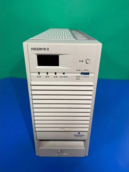
- Model Number: HD22010-2
- Manufacturer: Emerson Automation Solutions
- Input Voltage: 304-456V AC (Three-Phase Three-Wire)
- Output Voltage: 192-280V DC (Adjustable)
- Output Current: 10A Continuous, 10.5A Peak (105% Rating)
- Power Factor (PFC): ≥0.90 (Full Load)
- Efficiency: ≥92% (Full Load)
- Operating Temperature: -5°C to 50°C (23°F to 122°F)
- Cooling Method: Hybrid (Natural Convection + Forced Air)
- Protection Features: Input Over/Under Voltage, Output Over/Under Voltage, Short Circuit, Over Temperature, Phase Loss
- Communication: RS485 (Modbus RTU Protocol)
- Mounting: 19″ Rack-Mounted (Standard Substation DC Panel Compatibility)
- Hot-Swap Support: Yes (Online Maintenance)
- Display: Front-Panel LED (Voltage, Current, Fault Codes)
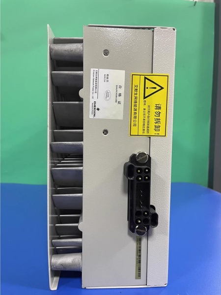
- Enclosure Material: Die-Cast Aluminum (Dust-Proof Design)
- Certifications: IEC 61000, CE, RoHS, GB/T 19826 (Substation Power Standards)

Emerson HD22010-2
Field Application & Problem Solved
In mid-voltage substation power systems—35kV to 220kV transmission/distribution substations, power plant auxiliary DC banks, and industrial facility emergency power setups—the biggest frustrations with legacy charging modules are narrow input ranges, low efficiency, and costly maintenance downtime. Old linear chargers waste energy (efficiency <82%), overheat in tight DC panels, and require full system shutdowns for repairs. Worse, their limited input voltage tolerance (±10% of nominal) causes frequent trips during grid fluctuations, leaving batteries undercharged and critical DC loads (protective relays, emergency lighting) vulnerable. Plants also lack visibility into charger health, with no way to detect component degradation until a sudden failure disrupts operations.
This HD Series charging module solves these pain points with its robust, substation-tailored design. It’s engineered to deliver consistent battery charging and DC power, even during grid sags or phase loss, while supporting hot-swap maintenance to eliminate downtime. You’ll find it in utility substations powering relay protection systems, power plants maintaining boiler control DC panels, and industrial facilities backing up emergency shutdown systems. I installed 24 of these at a Southwest 110kV substation where legacy chargers caused 6-8 grid-related trips yearly; post-installation, trips dropped to zero, and energy consumption from charging systems fell by 10%. The hot-swap feature let technicians replace a faulty module in 4 minutes without interrupting the DC bank—critical for 24/7 substation reliability.
Its core value is reliable, efficient power delivery with minimal operational disruption. Substations and industrial facilities can’t afford unplanned downtime—this module’s wide input range and robust protection ensure continuous operation, while its high efficiency reduces energy costs. Unlike legacy chargers, it supports remote monitoring via RS485, letting operators track voltage, current, and fault status from the control room. For maintenance teams, it eliminates shutdowns for repairs; for utility operators, it ensures backup power readiness; for plant managers, it cuts energy waste and extends battery life. It’s not just a charger—it’s the backbone of dependable DC power systems in mid-voltage critical infrastructure.
Installation & Maintenance Pitfalls (Expert Tips)
- Input Voltage Range Compliance: Rookies connect the module to voltages outside the 304-456V AC range (e.g., 280V AC during grid brownouts), triggering over/under voltage faults. A Midwest substation did this, causing the module to shut down and leave the battery bank uncharged. Verify input voltage with a multimeter before installation—if grid fluctuations are common, install a line conditioner to keep voltage within the module’s operating range. Never exceed 456V AC input, as this will damage the PFC circuit.
- Battery Bank Voltage Matching: Failing to adjust the output voltage to match the battery bank (e.g., 250V for 220V lead-acid batteries) causes undercharging or overcharging. A chemical plant set the output to 230V for a 220V battery bank, leading to reduced backup time during outages. Use the front-panel keypad to calibrate the output to the battery manufacturer’s recommended float charge level (typically 2.20-2.25V per cell for lead-acid). Verify with a calibrated multimeter before connecting to the battery bank.
- RS485 Address Conflict Avoidance: Using duplicate communication addresses (set via DIP switches) in multi-module networks causes data corruption. A Northeast power plant had 8 modules with the same address, making remote monitoring unusable. Set each module to a unique address (0-15 range) using the front-panel DIP switches—refer to the module’s wiring diagram to avoid misconfiguration. Test communication with a Modbus scanner before integrating with SCADA.
- Cooling Vent Maintenance: Neglecting to clean dust from the module’s air vents blocks airflow, leading to overheating and thermal shutdown. A coastal substation ignored this, with salt dust clogging vents causing 3 modules to fail during summer. Inspect vents quarterly—use low-pressure compressed air (25-30 psi) to blow out dust, directing air away from the module to avoid pushing debris inward. For dusty environments, install a dust filter over the vents (Emerson-compatible P/N 9199-00172).
EMERSON HD22010-2
Technical Deep Dive & Overview
The HD22010-2 is a three-phase high-frequency switching charging module engineered for mid-voltage substation and industrial DC power systems. At its core is a two-stage power conversion architecture: first, a three-phase passive PFC (Power Factor Correction) circuit conditions the input AC, reducing harmonic distortion and improving grid compatibility. This is followed by a high-frequency DC/DC converter (operating at 80kHz) that delivers a stable, adjustable 192-280V DC output—optimized for lead-acid and nickel-cadmium battery charging.
A dedicated microcontroller manages real-time monitoring and control, tracking input voltage, output current, internal temperature, and battery health. This enables rapid fault response: short circuit protection limits output current to ≤3.5A within 1ms, while over-temperature protection activates at 60°C to prevent component damage. The hybrid cooling system switches between natural convection (for loads <4A) and forced air (for higher loads), balancing efficiency and noise reduction—critical for substation control rooms where quiet operation is required.
The module’s RS485 interface supports Modbus RTU, enabling remote configuration and monitoring via SCADA or building management systems. Technicians can adjust charging parameters, view fault logs, and initiate self-tests without physical access, reducing maintenance time. The hot-swap design uses a tool-less latch and redundant power connections, ensuring the DC bank remains operational during module replacement—eliminating the downtime associated with legacy chargers.
Ruggedization features include a dust-proof die-cast aluminum enclosure, vibration-resistant components (rated for 2.5g shock), and a wide operating temperature range (-5°C to 50°C)—ideal for harsh substation environments. The module’s phase loss protection maintains 50% output capacity if one input phase fails, ensuring the battery bank continues charging until the fault is resolved.
What sets it apart is its balance of reliability and practicality for mid-voltage applications. Unlike generic chargers, it meets utility standards for compatibility with substation DC panels and battery banks, while its simplified maintenance features reduce operational costs. For field service engineers, it’s a workhorse that solves the key pain points of legacy charging systems—narrow input ranges, inefficient operation, and costly downtime. It’s not just a charging module—it’s a critical component that ensures the resilience of mid-voltage critical infrastructure.


