


Description
Hard-Numbers: Technical Specifications
- Probe Tip Diameter: 8 mm (0.315 in.)
- Linear Range: 2.0 mm (80 mils) from probe tip (typical gap range: 0.25mm to 2.25mm)
- Probe Body Diameter: 8 mm (0.315 in.) / 5/8-18 UNF-2A threaded mounting
- Probe Body Material: 316L stainless steel (probe housing), Inconel X-750 probe tip
- Probe Length: 45 mm (1.77 in.) from mounting face to tip
- Thread Length: 12.7 mm (0.5 in.)
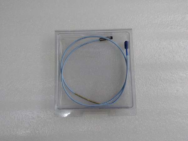
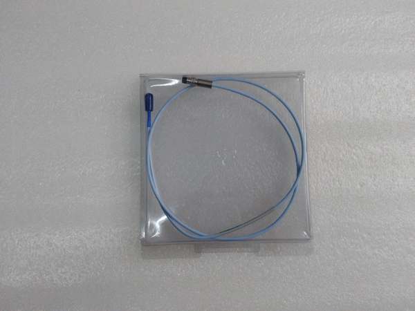
- Cable Configuration:
- Probe end: Fixed 0.5m integral cable
- Extension cable: Not specified (typically sold as complete probe assembly; extension added separately if needed)
- Total System Length (from probe to proximitor): 5m (16.4 ft) as indicated by “-045-” in model number
- Cable Type: 3300 XL series, high-flex, stainless steel overbraid shield, PTFE insulation
- Probe-to-Proximitor Compatibility: Requires 3300 XL Proximitor oscillator/demodulator (e.g., 330180-50-05)
- Supply Voltage: -24 VDC ±10% from Proximitor
- Input Current: Typically 12-15 mA at -24 VDC
- Output Signal:
- Gap Voltage: -2.0 to -18.0 VDC linear range (typical)
- Sensitivity: 7.87 V/mm (200 mV/mil) for 3300 XL system
- Frequency Response: DC to 10 kHz (within ±3dB)
- Temperature Range:
- Operating: -51°C to +177°C (-60°F to +350°F) with 3300 XL Proximitor
- Probe only: -51°C to +177°C (-60°F to +350°F)
- Cable: -40°C to +105°C (-40°F to +221°F)
- Pressure Rating: Up to 350 bar (5,000 psi) with proper mechanical seal
- Vibration Resistance: Up to 500 g shock, 50 g continuous vibration
- Immunity:
- EMI: >100 V/m radiated immunity (3300 XL improvement)
- Ground Loop: Common mode rejection >80 dB at 50/60 Hz
- Compliance:
- ATEX/IECEx: II 2G Ex ia IIC T4 Ga/T4 Gb (with suitable barriers)
- UL: Class I, Div 2, Groups A, B, C, D, T4
- CE: EN 60079 series (with barriers)
- Dimensions:
- Probe: 45 mm length × 8 mm diameter
- Cable: 5m total system length
- Weight: 0.35 kg (0.77 lb) probe + cable assembly
Bently 330105-02-12-10-02-CN
The Real-World Problem It Solves
You can’t protect rotating machinery without knowing the exact position of the shaft. This non-contact proximity probe converts the gap between probe tip and rotating shaft surface into a proportional DC voltage, giving you millimeter-accurate displacement data for vibration analysis, thrust position monitoring, and phase reference. It’s the difference between catching a bearing wipe in progress and discovering it only after catastrophic shaft-to-seal contact has destroyed your machine.
Where you’ll typically find it:
- Steam turbine generator sets in power plants, monitoring radial vibration on all journal bearings and axial thrust position
- Centrifugal compressors in gas processing plants, tracking shaft eccentricity and surge protection
- Boiler feed pumps and large motors in refineries, measuring bearing vibration and shaft position
- Hydro turbines in hydroelectric plants, monitoring guide bearing vibration and runner position
- Gearboxes and high-speed couplings in heavy industrial applications, detecting misalignment and wear
Bottom line: This is your eyes on the shaft—without accurate displacement data from these probes, your entire vibration monitoring system is blind, and you risk multi-million dollar equipment failures that could have been prevented with early detection.
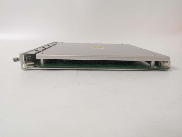
Hardware Architecture & Under-the-Hood Logic
The 330130-045-02-05 is a complete transducer assembly consisting of the 8mm proximity probe, integral cable segment, and (when configured with extension cable) the extension cable that connects to the Proximitor oscillator/demodulator. The probe contains an inductive sensing coil at its tip, while the Proximitor generates the high-frequency RF excitation and demodulates the returned signal to produce a DC voltage proportional to the gap.
- Proximitor Excitation: The 3300 XL Proximitor generates a high-frequency RF signal (typically 1.5 MHz) that travels through the probe cable to the probe tip coil.
- Inductive Sensing: The probe tip coil creates an electromagnetic field. When conductive shaft material enters this field (within the linear range), eddy currents are induced in the shaft surface, reducing the coil’s inductance.
- Gap-to-Voltage Conversion: The Proximitor detects the change in coil inductance and converts it to a DC output voltage using synchronous demodulation. The relationship between gap and voltage is linear within the 2.0mm (80 mil) linear range.
- Signal Characteristics:
- Linear Range: From approximately 0.25mm to 2.25mm gap, output varies linearly from -2.0V to -18.0V (7.87 V/mm sensitivity)
- Slope: 7.87 V/mm (200 mV/mil) for 3300 XL system
- Null Point: Typically at 0.75mm to 1.25mm gap (varies by system configuration)
- Cable Architecture: The probe’s integral 0.5m cable connects to an extension cable (if used), which then connects to the Proximitor. The 3300 XL system maintains tight capacitance tolerance (+/- 3% or better) to ensure consistent sensitivity across different cable lengths. The “-045-” designation indicates a 5m total system length from probe to Proximitor.
- Shielding and Grounding: The cable has a stainless steel overbraid shield with a drain wire. The shield must be grounded at the Proximitor end only to prevent ground loops. The probe body is isolated from the cable shield (isolated tip construction) to minimize ground path interference.
- Temperature Compensation: The 3300 XL system includes automatic temperature compensation in the Proximitor to minimize drift across the operating temperature range. The probe’s 316L stainless steel housing and Inconel tip provide excellent thermal stability.
Bently 330105-02-12-10-02-CN
Field Service Pitfalls: What Rookies Get Wrong
Wrong Gap Voltage at CommissioningTechs set the probe gap voltage to -7.0V (the “classic” 3300 system value) on a 3300 XL system, then wonder why the vibration readings are off-scale or the probe saturates during large amplitude vibration.
- Field Rule: For 3300 XL systems, target a gap voltage of approximately -9.0V to -10.0V at the shaft position where you’ll operate. This centers the vibration within the 2.0mm linear range. The older 3300 systems used -7.0V, but 3300 XL has different characteristics due to improved probe design. Always check the Proximitor’s calibration curve for your specific probe/cable combination.
Mixing Probe and Cable Lengths Without RecalibrationReplacing a 5m probe system with a 3m or 7m system and assuming the sensitivity (200 mV/mil) stays the same, then discovering vibration readings are 10-20% off.
- Field Rule: The 3300 XL system maintains tight capacitance tolerance, but you MUST recalibrate the monitor’s input scale when changing cable lengths. The 3500 monitor configuration software includes probe type and cable length parameters—update these and verify the scale factor with a mechanical calibration (target block or dial indicator) if precision is required. Sensitivity can vary ±2-3% between different cable lengths.
Incorrect Shield GroundingGrounding the cable shield at both the probe end and the Proximitor end, creating a ground loop that introduces 50/60Hz noise and erratic vibration readings.
- Quick Fix: Ground the shield ONLY at the Proximitor end (at the terminal block). Leave the probe end floating (ungrounded). The 3300 XL cables have a stainless steel overbraid with a drain wire—connect the drain wire to the Proximitor’s chassis ground terminal. For hazardous areas, follow the barrier manufacturer’s grounding scheme, but still maintain single-point grounding where possible.
Over-torquing Probe Mounting ThreadsUsing excessive force when tightening the 5/8-18 probe into the bracket or housing, stripping the threads or distorting the probe body, which affects the alignment and can cause early failure.
- Field Rule: Torque the 5/8-18 threaded probe to 4.5-6.8 N·m (40-60 in-lbs) maximum. Use a torque wrench for critical installations. Do NOT use pipe sealant or Teflon tape on the threads—these can affect electrical isolation. For high-vibration applications, consider a jam nut or locknut to prevent loosening, but don’t over-tighten.
Ignoring the Linear Range LimitsAssuming the probe works from 0mm to 2.5mm gap, then getting non-linear readings or saturation when the probe is positioned outside the 0.25mm to 2.25mm linear range.
- Field Rule: The linear range is strictly 2.0mm (80 mils) within the probe’s sensing zone. Position the probe tip so that at normal operating shaft position, you have approximately 1.25mm (50 mils) of gap, giving you ±0.5mm (±20 mils) of vibration travel before hitting non-linear regions. Monitor the gap voltage—anything outside -2V to -18V is outside the linear range.
Forgetting to Verify Proximitor CompatibilityConnecting a 3300 XL probe to an older 7200 series Proximitor or vice versa, then wondering why the sensitivity and gap voltage relationships don’t match the spec sheet.
- Field Rule: 3300 XL probes require a 3300 XL Proximitor (e.g., 330180-50-05). Older 3300 or 7200 Proximitors have different characteristics and are not interchangeable. The Proximitor model number is printed on the label—look for “330180” to confirm XL compatibility. Mismatched systems will work but with reduced accuracy and shifted linear range.
Neglecting Mechanical Runout CompensationMeasuring vibration on a shaft with visible mechanical runout (surface imperfections, scratches, residual magnetism) and reporting total vibration instead of compensated (electrical runout removed) values.
- Field Rule: Use the 3500 monitor’s mechanical runout compensation feature (slow roll compensation) to subtract mechanical imperfections from the vibration signal. Perform a slow roll (barring gear) at 50-100 RPM, record the runout vector, and configure the monitor to subtract this from running vibration. This is critical on older machines with worn bearing journals.
Commercial Availability & Pricing Note
Please note: The listed price is for reference only and is not binding. Final pricing and terms are subject to negotiation based on current market conditions and availability.

