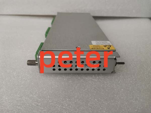
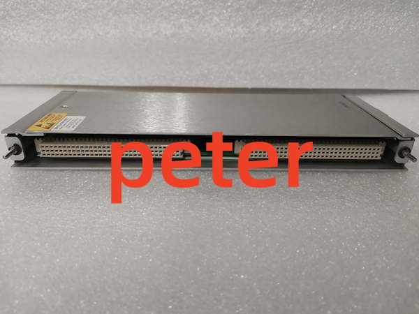
Description
Product Core Brief
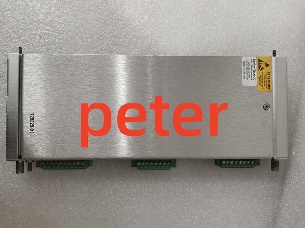
- Model: 128229-01
- Brand: Bently Nevada
- Series: 3500 Machinery Protection System
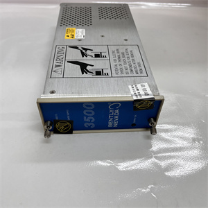
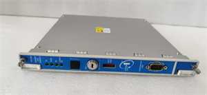
- Core Function: Serves as the front-panel I/O termination card for 3500/42M vibration and position monitoring modules.
- Product Type: Prox/Seismic I/O Module (Front Card)
- Key Specs: Front-Panel BNC Connectors | Internal Terminations | 3500/42M Compatible
- Note: Verify compatibility with specific 3500/42M rear card revisions before ordering.
Key Technical Specifications
| Parameter | Specification |
|---|---|
| Product Type | Prox/Seismic I/O Module (Front Card) |
| System Compatibility | Bently Nevada 3500/42M Monitor |
| Connector Type | Front-Panel BNC (Coaxial) |
| Termination | Internal Terminations |
| Function | Signal routing, buffering, and front-panel access |
| Form Factor | 3500 Front Card Assembly |
| Weight | 0.764 lbs (approx.) |
| Application | Displacement, velocity, and acceleration monitoring |
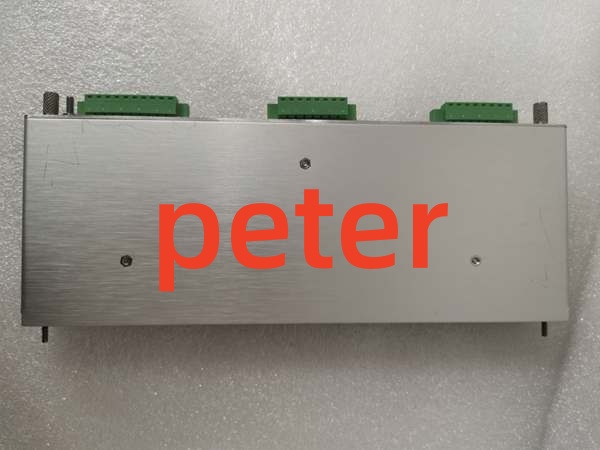
Bently Nevada 128229-01
Product Introduction
The 128229-01 is a dedicated front-panel I/O card designed for the Bently Nevada 3500/42M displacement, velocity, and acceleration monitor. It provides the physical BNC connector interface for routing Proximitor and seismic sensor signals into the main processing board.
This module features internal terminations and buffered signal paths to maintain signal integrity in high-noise industrial environments. It acts as the primary user-accessible interface for connecting field instrumentation directly to the 3500 rack.
QA & Testing SOP (Transparency Building)
- Incoming Inspection: Verify part number 128229-01 against OEM documentation. Inspect the front-panel BNC connectors for physical damage, stripped threads, or internal center-pin deformation. Check the PCB for micro-fractures or corrosion.
- Live Testing: Mate with a verified 3500/42M rear card in a test rack. Inject a calibrated vibration signal into the BNC input and verify signal routing to the backplane using System 1 software.
- Electrical Testing: Measure insulation resistance between BNC shield and signal pin (>10MΩ). Verify grounding continuity across the front panel chassis. Check buffer circuit output levels with a calibrated Fluke 115.
- Hardware Verification: Confirm all mounting standoffs and internal ribbon cable connections are secure. Inspect the mating connector pins for straightness and oxidation.
- Final QC & Packaging: Clean BNC connectors with approved contact cleaner. Package in anti-static shielding with desiccant. Attach QC pass tag with test date, signal verification results, and technician ID.
Installation Pitfalls & Guide (Engineer to Engineer)
❗ Rear Card Mismatch: The 128229-01 front card must match the specific revision of your 3500/42M rear card. Never mix incompatible front/rear card combinations. Doing so can cause signal routing errors, improper termination, or backplane communication failures. Always verify the rear card part number first.
❗ BNC Connector Damage: The front-panel BNC connectors are highly sensitive to mechanical abuse. Never use excessive force when connecting or disconnecting sensor cables. Stripped threads or bent center pins are common field failures that require complete card replacement.
❗ Internal Ribbon Cable Stress: This front card connects to the rear processing card via an internal ribbon cable. When installing, ensure the ribbon cable is not pinched, folded, or stressed. A damaged ribbon cable causes intermittent signal loss that is nearly impossible to diagnose in the field.
❗ ESD Dangers: The buffered signal circuits on this I/O card are extremely sensitive to electrostatic discharge. A static zap from an ungloved hand can destroy the input buffer ICs without visible damage. Always wear a grounded wrist strap when handling this module.
❗ Ground Loop Issues: The front panel BNC shields are tied to the module chassis ground. If your sensor cables have separate grounding at the probe end, you risk creating a ground loop that introduces 60Hz hum into your vibration readings. Verify your grounding scheme before installation.
Replacement Guide:
- Pre-install: Document existing sensor wiring and verify rear card compatibility. Disconnect all field cables from the front panel. Ground yourself.
- Removal: Remove the front panel mounting screws. Carefully separate the front card from the rear card, ensuring the internal ribbon cable is not damaged.
- Install: Align the new front card with the rear card connector. Press evenly until fully seated. Reinstall mounting screws and reconnect field cables.
- Power-on Test: Verify sensor signal quality in System 1 software. Check for proper gap voltage (prox) or signal level (seismic). Confirm no new alarms are active before returning to service.
FAQ (Frequently Asked Questions)
Q: Can I hot-swap this I/O front card?
A: No. The 128229-01 does not support hot-swapping. Disconnecting the front card while the 3500/42M is powered will cause open-circuit conditions on the sensor inputs, potentially triggering false Danger alarms or damaging the buffer circuits. Always schedule a maintenance window and de-energize the module.
Q: What is the difference between 128229-01 and 176449-02?
A: The 128229-01 is specifically the front-panel I/O card with BNC connectors and internal terminations. The 176449-02 is typically a complete 3500/42M Proximitor/Seismic Monitor assembly (front and rear card combined). Verify whether you need just the front I/O card or the complete monitor module.
Q: Why am I getting erratic gap voltage readings after replacement?
A: This is usually caused by improper BNC connector seating, damaged sensor cable, or a mismatched front/rear card combination. Verify the BNC connection is fully seated and locked. Check the sensor cable for damage. Confirm the front card part number matches your rear card revision exactly.
Q: Can I use this front card with a 3500/40M monitor?
A: No. The 128229-01 is designed exclusively for the 3500/42M displacement/velocity/acceleration monitor. The 3500/40M uses a different I/O architecture and connector configuration. Cross-compatibility will result in mechanical fitment failure and electrical incompatibility.
Q: What happens if I lose the BNC connector threads?
A: Do not attempt to repair stripped BNC threads with tape or adapters. This creates an unreliable connection that will fail under vibration. Replace the entire 128229-01 front card. Field repairs on BNC connectors are not supported and will compromise signal integrity.
Q: Is this part still manufactured by Bently Nevada?
A: The 3500 system remains an active product line, and the 128229-01 is a standard component. However, always verify current OEM availability and lead times. For legacy installations, New Original or New Surplus inventory is typically available through authorized distributors.
Q: Why does my sensor signal have excessive noise after installing this card?
A: Check for ground loops, improper cable shielding, or EMI interference. Verify that the BNC shield is properly grounded at the front panel. Ensure sensor cables are routed away from VFDs and high-current conductors. Also verify that the internal ribbon cable is properly seated and not damaged.