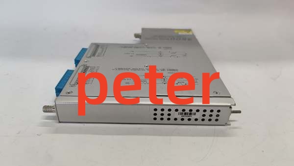
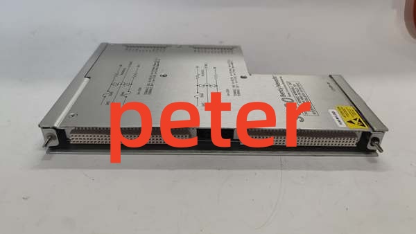
Description
Product Core Brief
- Model: 135489‑04
- Brand: Bently Nevada
- Series: 3500 Machinery Protection System (3500/40M, internal‑barrier, internal‑termination variant)
- Core Function: Four‑channel proximity‑only monitor module with factory‑integrated intrinsic‑safety barriers and onboard screw‑style field terminals. It only accepts eddy‑current proximity probe inputs; seismic transducers are not supported on this hardware. It performs local signal conditioning, sensor fault detection, and user‑configurable alert/danger alarm thresholds. Measurement and alarm status publish across the rack backplane to communication gateway and relay modules for rotating‑machinery protection. Integrated barriers eliminate requirement for external zener barrier assemblies for hazardous‑classified transducer wiring runsMade-in-Ch….
- Product Type: 4‑Channel Proximitor‑Only Monitor Module, Internal‑Barrier / Internal Termination
- Key Specs: 4 independently‑configurable proximity‑input channels | Full‑height slot | Built‑in IS barriers | Proximity‑probe‑only (no seismic support) | On‑board Euro‑style terminal blocks
Note: OEM discontinued; available as new surplus and field‑tested used stock.
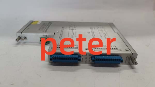
BENTLY 135489‑04
Key Technical Specifications
- Input Channels: 4 multi‑function proximity‑input channels, configured in pairs (CH1‑2, CH3‑4)
- Supported Transducers: 3300‑series eddy‑current proximity probes (seismic transducers, accelerometers, velocity sensors are not compatible with 135489‑04)
- Measurement Modes: Radial vibration, thrust position, differential expansion, eccentricity, REBAM
- Input Frequency Range: 0.5 Hz to 12 kHz
- Safety Feature: Integrated intrinsic‑safety barriers for hazardous‑area transducer circuits; no external barrier hardware required
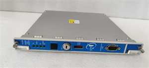
- Field Termination: Direct‑mount Euro‑style screw terminal blocks on module front face
- Backplane Power Draw: 340 mA @ +24 VDC
- Form Factor: Full‑height slot for 3500‑series rack; single‑piece integrated assembly, no separate rear‑plane board
- Analog Output: 4‑20 mA per channel for process‑system host interfacing
- Alarm Logic: Software‑programmable Alert / Danger setpoints; sensor‑fault detection per channel‑pair
- Operating Temperature: ‑30 °C to +65 °C
- Storage Temperature: ‑40 °C to +85 °C
- Weight: 0.45 kg
- Dimensions: 241 mm × 99 mm × 24.4 mm
- Humidity: 5‑95 % non‑condensing
- Compliance: API 670; ATEX / IECEx certified for hazardous‑location installation when deployed per Bently Nevada barrier installation manual.
Product Introduction
135489‑04 is the internal‑barrier variant of the 3500/40M Proximitor‑only monitor. It is physically similar to the 135489‑01 (3500/42M), but does not support seismic‑transducer inputs. All four channels are dedicated exclusively to eddy‑current proximity‑probe signals.
On‑board intrinsic‑safety barriers limit energy delivered to field‑mounted proximity probes. This removes separate external barrier panels and simplifies cabinet wiring for installations where probe cables run into classified hazardous zones. Channels are configured in pairs; each pair can run one measurement function. Two distinct measurement functions can execute on one module simultaneously.
All alarm‑threshold comparisons execute locally on‑board. Alarm and trip status propagate across rack backplane to relay output modules. Vibration‑position data flows to the 3500/92 gateway for DCS/PLC and System 1 host access. Common deployments include steam‑turbine bearing‑vibration supervision, centrifugal‑compressor thrust‑position monitoring, and critical‑generator protection. This module is a complete integrated front‑and‑rear assembly; no mating rear‑plane board is needed.
QA & Testing SOP
- Incoming Inspection: Match part‑number and serial‑number against OEM documentation. Inspect screw terminals, backplane edge connector, PCB traces and intrinsic‑safety‑barrier identification labeling for damage or counterfeit marking inconsistencies. Log serial numbers for traceability.
- Live Testing: Seat inside genuine 3500 rack, apply rated backplane power. Establish communications with rack‑configuration software. Inject calibrated simulated proximity‑probe signals to each channel‑pair. Validate position‑vibration readings, sensor‑fault reporting, alarm‑threshold triggering, and 4‑20 mA output stability during continuous 24‑hour load test. Seismic‑transducer simulation inputs shall produce channel‑fault flags as expected for this proximitor‑only hardware.
- Electrical Testing: Use Fluke 115 and insulation tester. Verify >10 MΩ isolation between field‑signal circuits and chassis ground. Confirm chassis‑to‑rack‑earth continuity.
- Firmware / Config Backup: Record exact firmware revision loaded on the unit. Capture screenshots of channel‑pair assignments, measurement‑mode selections, alarm‑setpoints, and 4‑20 mA scaling before reset. Photograph front‑panel LED layout and terminal‑block pin‑out for reference records.
- Final QC & Packaging: Place unit inside anti‑static shielding bag. Apply printed QC‑pass tag with test‑date stamp. Pack with shock‑absorbent foam for transit.
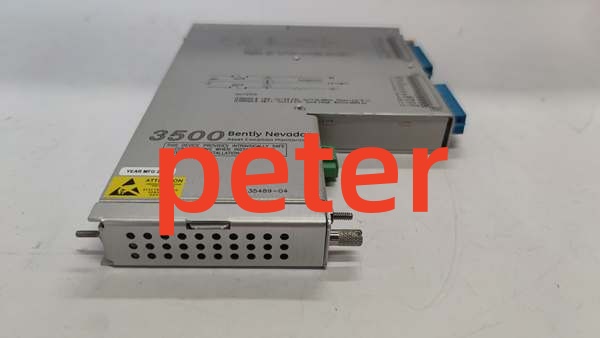
BENTLY 135489‑04
Installation Pitfalls & Guide
❗ Firmware‑Rev Mismatch: Mismatched rack‑firmware and module‑firmware produces incorrect measurement values, false channel‑fault flags or unreliable alarm‑logic execution. Confirm firmware compatibility before commissioning machinery‑protection functions.❗ Slot‑Location Error: This hardware occupies a full‑height rack slot. Partial seating breaks backplane communications and disables protection‑monitoring capability. Photograph existing hardware layout prior to removal.❗ Wiring‑Incompatibilities: This module works only with proximity probes. Seismic‑transducer wiring connected to this unit will trigger persistent channel‑fault alarms. When deployed for hazardous‑area service, strictly follow OEM intrinsic‑safety installation rules for cable types and maximum cable lengths. Mis‑termination yields invalid readings and defeats hazardous‑area safety compliance. Cross‑reference OEM datasheet before landing field wiring.❗ Power‑Draw Changes: Adding this full‑height module increases total rack backplane load. Calculate aggregate slot‑by‑slot current consumption to avoid overloading rack power supplies on protection‑critical racks.❗ ESD Dangers: Unprotected handling can destroy precision analog‑conditioning and intrinsic‑safety‑barrier circuits. Always use grounded ESD wrist straps during handling and replacement.
4‑step replacement guide1. Pre‑install: De‑energize rack power, don ESD wrist strap. Validate rack‑firmware‑revision compatibility. Document channel‑pair assignments, alarm‑setpoints, 4‑20 mA scaling and all field‑wiring terminations. Review hazardous‑area installation compliance requirements.2. Removal: Release front‑panel latch, slide out old unit, document each field‑wire termination.3. Install: Slide replacement firmly into target full‑height rack slot until latch fully engages. Re‑connect proximity‑probe field wiring following barrier‑compliant pin‑out rules from OEM datasheet. Do not connect seismic‑type transducers.4. Power‑on Test: Restore rack power, confirm module OK‑LED status. Inject simulated proximity‑probe signals. Validate measurement readings, sensor‑fault reporting, alarm‑threshold behavior and 4‑20 mA output. Perform full‑functional proof‑test before returning machinery‑protection functions to service.
FAQ
Q: Does this unit support hot‑swap operation?A: No. It draws power directly from the main system backplane. Live removal creates voltage transients that can corrupt adjacent monitoring cards or damage backplane traces. Full rack‑power shutdown is mandatory.
Q: What differentiates 135489‑04 (3500/40M) from 135489‑01 (3500/42M)?A: 135489‑04 is proximitor‑only; it accepts proximity‑probe inputs only, seismic transducers are not supported. 135489‑01 (3500/42M) supports both proximity probes and seismic transducers. Both variants carry integrated intrinsic‑safety barriers and internal‑termination screw terminals.
Q: Can I mix proximity‑probe and seismic‑transducer inputs on 135489‑04?A: No. This hardware does not support seismic‑transducer inputs. Connecting seismic‑transducer signals will result in constant channel‑fault status.
Q: What happens when stored configuration is lost after power‑cycle?A: All channel‑pair‑mode assignments, alarm‑thresholds and scaling‑parameters reside in volatile memory. Power loss erases custom settings. Reload rack‑configuration after power restoration.
Q: Is brand‑new factory stock available?A: Original OEM manufacturing has ceased. Available stock comes from new‑surplus or field‑tested used inventory. Lead‑times shift with lot availability.
Q: What warranty applies to surplus stock?A: Third‑party inventory carries limited‑time functional warranty covering hardware defects. It excludes damage caused by site‑side surge events, mis‑wiring, or incorrect configuration. OEM factory warranty is no longer offered.
Q: Can a 3500/42M module serve as direct drop‑in replacement for 135489‑04?A: Mechanically form‑factor matches. Functionally, 3500/42M adds seismic‑input capability. If your site uses only proximity probes, substitution is possible, but you must re‑validate all channel configuration and hazardous‑area barrier‑certification compatibility.
Q: Can this module be used for TMR voting configurations?A: Yes. Three identical 135489‑04 modules must occupy rack slots designated for triple‑modular‑redundant deployment. Site‑specific grounding, cable‑routing and hazardous‑area compliance must be reviewed.