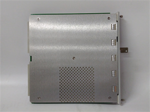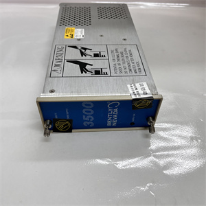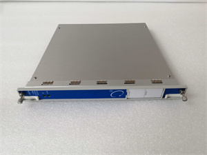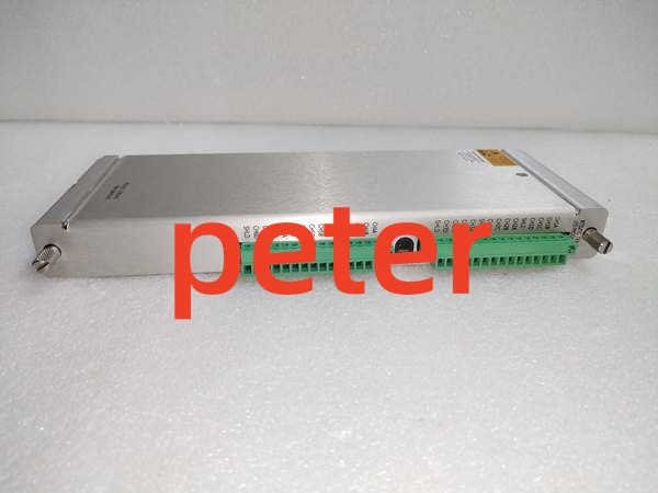

Description
Product Core Brief
- Model: 133819‑01
- Brand: BENTLY Nevada
- Series: 3500 Machinery Protection System (3500/60)
- Core Function: Multi‑channel temperature monitor module accepting RTD and thermocouple inputs. It processes temperature readings, executes user‑defined alert and danger alarm thresholds, and transmits temperature data across the rack backplane for rotating‑machinery condition monitoring. No per‑channel analog recorder outputs are built into this variant.
- Product Type: Non‑Isolated RTD / TC Temperature Monitor Module
- Key Specs: 6 configurable input channels | Full‑height slot | Mixed RTD / TC channel assignment supported | Non‑isolated field inputs
Note: OEM discontinued; available as new surplus and field‑tested used stock.
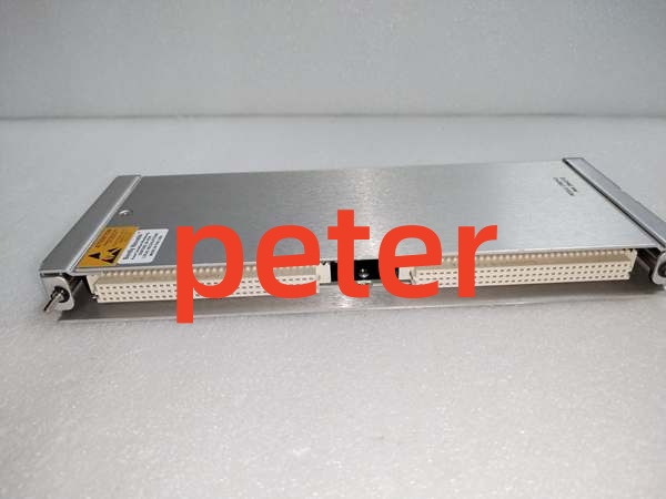
BENTLY 133819‑01
Key Technical Specifications
- Input Channels: 6 multi‑function temperature input channels
- Supported Sensors: PT100 RTD, multiple thermocouple types (J, K, T, E, R, S, B, N)
- Configuration: Each channel independently set for RTD or thermocouple via 3500 configuration software
- Input Isolation: Non‑isolated channel‑to‑channel
- Backplane Power Draw: 320 mA @ +24 VDC
- Form Factor: Full‑height slot for 3500‑series rack
- Measurement Range: Driven by sensor type selection within configuration tool
- Alarm Logic: Software‑programmable Alert / Danger setpoints; rate‑of‑change alarms
- Backplane Output: Temperature values, alarm and channel‑fault status sent to rack gateway and other rack modules
- Operating Temperature: 0 °C to +60 °C
- Storage Temperature: ‑40 °C to +85 °C
- Weight: 0.40 kg
- Dimensions: 242 mm × 112 mm × 25 mm
- Humidity: 5‑95 % non‑condensing
- Compliance: API 670 machinery‑monitoring requirements; TMR‑capable when installed in groups of three for triple‑modular‑redundant deployments.
Product Introduction
This 3500/60 module delivers temperature‑monitoring capability inside the 3500 rack. It handles bearing metal temperature, casing temperature and other thermal‑sensor inputs from turbines, compressors and auxiliary equipment. Each channel can be set for either RTD or thermocouple, mixed‑sensor layouts on one module are allowed.
Unlike the 3500/61 variant, this 133819‑01 does not provide per‑channel 4‑20 mA recorder outputs. All measured data propagates across the rack backplane and exits the system through the rack communication gateway. It supports TMR installation for high‑availability condition‑monitoring setups, though channel‑to‑channel isolation is not present on this non‑isolated hardware revision.
QA & Testing SOP
- Incoming Inspection: Match part number and serial number against OEM documentation. Inspect field‑signal terminals, edge connectors and PCB for trace damage or counterfeit marking inconsistencies. Log serial numbers for traceability.
- Live Testing: Seat inside genuine 3500 rack, apply rated backplane power. Establish comms handshake with rack configuration software. Inject calibrated RTD and thermocouple simulation signals to each channel; validate temperature readings, alarm trigger thresholds and fault‑flag reporting through continuous 24‑hour load test.
- Electrical Testing: Use Fluke 115 and insulation tester. Verify >10 MΩ isolation between module backplane and chassis ground. Confirm chassis‑to‑rack‑earth continuity.
- Firmware/Config Backup: Record exact firmware revision loaded on the unit. Capture screenshots of sensor‑type assignments, temperature ranges and alarm setpoints before reset. Photograph front‑panel LED layout for reference records.
- Final QC & Packaging: Place unit inside anti‑static shielding bag. Apply printed QC pass tag with test‑date stamp. Pack with shock‑absorbent foam for transit.
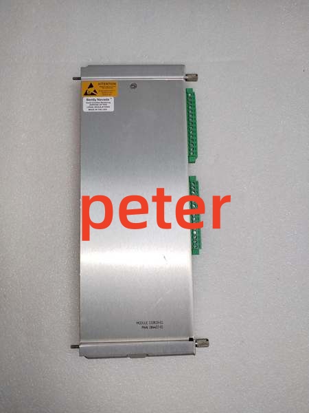
BENTLY 133819‑01
Installation Pitfalls & Guide
❗ Firmware Rev Mismatch: Mismatched rack and module firmware creates incorrect temperature readings or false channel‑fault indications. Confirm firmware compatibility before commissioning.❗ Slot Location Error: This hardware requires a full‑height rack slot. Partial seating breaks backplane communications. Photograph old hardware layout prior to removal.❗ Wiring Incompatibilities: RTD 3‑wire connections and thermocouple polarity are critical. Reversed thermocouple polarity yields offset readings; incorrect RTD wiring produces invalid temperature values. Cross‑reference OEM datasheet before landing field wiring. Since this is non‑isolated version, avoid mixing large‑ground‑potential difference sources on adjacent channels.❗ Power Draw Changes: Adding this full‑height module increases total rack backplane load. Calculate aggregate slot‑by‑slot current consumption to avoid overloading rack power supplies.❗ ESD Dangers: Unprotected handling can destroy precision analog measurement circuits. Field cases show ESD‑damaged spare units valued over $2000 before power‑on. Always use grounded ESD wrist straps.
4‑step replacement guide1. Pre‑install: De‑energize rack power, don ESD wrist strap, validate firmware compatibility. Document channel sensor assignments, temperature ranges and alarm setpoints from existing unit.2. Removal: Release front‑panel latch, slide out old unit, document every field‑wiring assignment and polarity.3. Install: Slide replacement firmly into full‑height slot until latch fully engages. Re‑connect field wiring respecting RTD wire order and thermocouple polarity per datasheet pinout.4. Power‑on Test: Restore rack power, confirm backplane communication. Inject simulated temperature signals to verify readings, alarm activation and fault reporting. Re‑validate all channel configurations before returning to service.
FAQ
Q: Does this unit support hot‑swap operation?A: No. It draws power directly from the main system backplane. Live removal creates voltage transients that can corrupt adjacent monitoring cards or damage backplane traces. Full rack power shutdown is mandatory.
Q: Can I run RTD and thermocouple sensors on different channels of the same 133819‑01?A: Yes. Each channel is independently configurable. Verify each channel setting after module replacement. Keep in mind this is non‑isolated hardware; large ground offsets between sensors can introduce measurement noise.
Q: What is the difference between 3500/60 (133819‑01) and 3500/61?A: The 3500/61 provides individual 4‑20 mA recorder outputs for each temperature channel. The 133819‑01 (3500/60) has no hardware recorder outputs; temperature data is only available via rack backplane and communications gateway.
Q: What happens when stored configuration is lost after power‑cycle?A: All sensor‑type assignments, temperature ranges and alarm thresholds live in volatile memory. Power loss erases custom parameters. Reload rack configuration after power restoration.
Q: Is brand‑new factory stock available?A: Original OEM manufacturing has ceased. Available stock comes from new‑surplus or field‑tested used inventory. Lead‑times shift with lot availability.
Q: What warranty applies to surplus stock?A: Third‑party inventory carries limited‑time functional warranty covering hardware defects. It excludes damage caused by site‑side over‑voltage events, mis‑wiring, or incorrect configuration. OEM factory warranty is no longer offered.
Q: Can this module be used for TMR configurations?A: Yes. Three identical 3500/60 modules must occupy adjacent rack slots for TMR voting. This non‑isolated hardware does not add channel‑to‑channel galvanic separation; site‑level grounding practices must be evaluated.
Q: Can isolated‑temperature‑monitor cards serve as direct drop‑in replacements?A: Physical form factor matches, but isolation properties differ. Direct swap is mechanically possible, but ground‑loop risk and system‑isolation requirements must be re‑evaluated for the field installation.