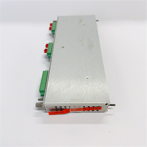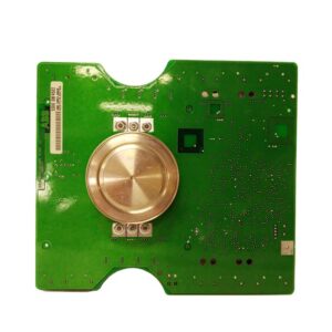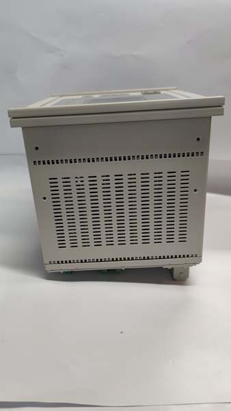
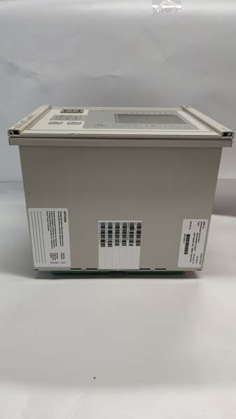
Description
Product Core Brief
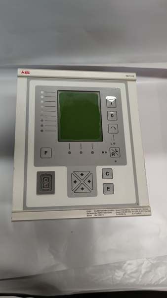
- Model: REF543KM127AAAA
- Brand: ABB
- Series: REF543 Medium Voltage Feeder Terminal
- Core Function: High-density multi-function bay protection terminal with licensed differential and distance protection, delivering feeder/transformer/motor protection, breaker control, metering and integrated FUPLA substation automation logic for 3–36 kV switchgear.
- Product Type: High-Count I/O Multi-Functional MV Protection & Control Terminal
- Key Specs: 25 Digital Inputs | 18 Trip/Control Output Relays | PS1 universal 80–265 V AC/DC auxiliary supply
- Note: Full end-of-production since 2022; limited factory new residual stock and fully bench-tested surplus available for legacy utility substation maintenanceABB Group.
Key Technical Specifications
| Parameter | Value |
|---|---|
| Full Order Code | |
| Auxiliary Power Variant | PS1 universal 80–265 V AC/DC; peak 35 W power draw |
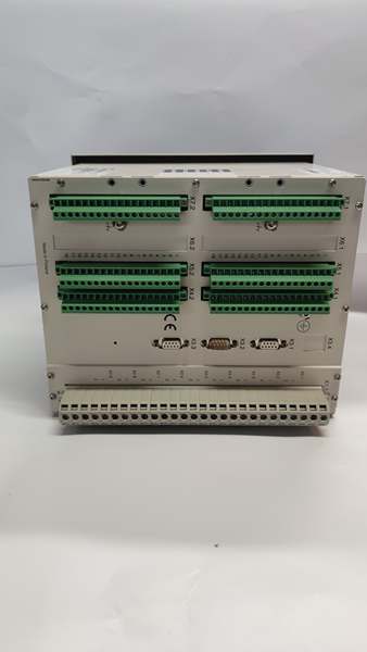
| Analog Measurement Channels | 9 galvanically isolated CT/VT inputs; 1A/5A CT selectable, 100 V VT rated |
| Binary I/O Layout | 25 isolated digital status inputs; 18 power relay outputs (fast trip + breaker control) |
| Standard ANSI Protection Suite | 50/51 overcurrent, 67 directional OC, 51N/67N earth fault, 49 thermal overload, 27/59 voltage, 25 synchro-check, 50BF breaker failure, fault locator, negative sequence unbalance |
| Licensed Optional Functions | Transformer differential (87), feeder distance protection (21), arc flash detection |
| Native Communication Interfaces | SPA fiber/RS485, LON fiber, IEC 60870-5-103 fiber; IEC 61850 via SPA-ZC400 adapter; Modbus TCP/RTU, Profibus DP, DNP3.0 via expansion modulesABB Group |
| Automation Logic Engine | FUPLA functional block programming fully IEC 61131-3 compliant for bay interlocks and auto-reclosing sequences |
| Non-Volatile Event Storage | 300 timestamped fault and operational records; breaker cycle counters retained through full auxiliary power loss |
| Front Panel Enclosure Rating | IP54 flush cabinet mount; rear terminal compartment IP20 |
| Operating Ambient Temperature | -10 °C to +55 °C panel mounted; performance derate above 50 °C |
| Storage Temperature Range | -40 °C to +70 °C |
| Mechanical Form Factor | 6U half-width 19-inch panel mount |
| Physical Dimensions | 224 mm W × 266 mm H × 238 mm D |
| Net Unit Weight | 7.7 kg fully assembledABB Group |
| Compliance Standards | IEC 60255, IEC 61131-3, IEC 61850, UL508, 4kV EMC surge immunity |
Product Introduction
This terminal is the high I/O count universal auxiliary supply variant of the REF543 platform, built for complex double-busbar substation bay schemes requiring extensive binary signal monitoring and breaker control capacity. The KM suffix designates the PS1 wide-range AC/DC power supply, separating it from KB low-voltage DC auxiliary variantseero.
Dual fiber SPA/LON communication links eliminate electromagnetic interference over long substation cable runs, while integrated fault locator algorithms deliver precise short-circuit distance calculation to cut field outage diagnostic time. Embedded FUPLA logic removes reliance on external auxiliary relay racks for custom bay interlocking, auto-reclosing and sequence control workflows. All metering, fault waveform and breaker cycle data persists in onboard flash memory during complete auxiliary supply outages.
QA & Testing SOP (Transparency Building)
- Incoming Inspection: Cross-reference full model code against OEM spare registry to reject counterfeit hardware; inspect LCD mimic panel, fiber transceiver ports and rear terminal screw blocks for scratches, discoloration or moisture residue; log serial numbers and production batch codes for full traceability records.
- Live Testing: Mount unit to standard 19-inch test rack, supply regulated 220 VAC/DC auxiliary power, inject multi-stage CT/VT analog fault signals, run continuous 24-hour protection element cycling and SPA/LON fiber communication stress testing with full event log validation.
- Electrical Testing: Use Fluke 115 multimeter and insulation tester to verify chassis ground resistance below 0.5Ω and isolation resistance above 10MΩ between auxiliary power, analog measurement and binary circuit groups.
- Firmware/Config Backup: Record exact embedded firmware revision via REF542conf configuration tool, photograph front-panel communication DIP switch address settings, export complete protection setting groups and FUPLA automation logic to encrypted offline storage.
- Final QC & Packaging: Clean LCD surface with anti-static microfiber cloth, cap fiber ports with dust protection plugs, cover screw terminals with insulating caps, seal unit inside ESD shielding bag, attach printed QC test tag with technician ID and full test runtime timestamp before foam-lined transit carton packaging.
Installation Pitfalls & Guide (Engineer to Engineer)
❗ Firmware Version Mismatch: Firmware builds newer than site REF542conf software block full FUPLA logic upload and disable directional differential protection element calculation; cross-check OEM software compatibility matrix before downloading parameter sets.❗ CT Open-Circuit Safety Hazard: Disconnecting current transformer wiring while the relay remains energized generates lethal high secondary voltage; short all CT terminals before disassembly per substation lockout/tagout protocols.❗ SPA/LON Fiber Bus Address Conflicts: Duplicate bay node addressing floods substation communication bus with broadcast traffic; capture high-resolution photos of original front-panel DIP switch layout prior to removal.❗ Auxiliary Supply Underrating: The unit draws peak 35 W during simultaneous trip output actuation; shared cabinet DC power supplies with multiple protection relays trigger voltage sag and incomplete relay boot sequences.❗ ESD Dangers: Unwristed technician contact with rear exposed PCB traces corrupts flash-based protection settings and real-time clock backup circuits; field service logs show ungrounded handling destroyed this terminal with over $5,400 in hardware and substation outage labor costs.
4-step replacement guide:
- Pre-install: Lock out and tag out substation auxiliary supply, short all CT secondary wiring, fit certified anti-static wrist strap, photograph analog CT/VT wiring, binary DI/DO terminal routing and fiber communication DIP switch positions.
- Removal: Unfasten rear terminal screw blocks, disconnect SPA/LON fiber jumpers, release front panel mounting latches, slide the unit forward out of the 6U rack cutout.
- Install: Seat new unit flush to panel frame, lock mounting latches, replicate original DIP communication address settings, reterminate all CT/VT, DI/DO and fiber bus wiring, remove CT shorting jumpers post-termination.
- Power-on Test: Restore auxiliary supply power, upload matching firmware and protection setting groups, inject simulated short-circuit and earth fault signals to validate trip element operation, confirm event logging and stable SCADA communication via SPA fiber bus.
FAQ (Frequently Asked Questions)
Q: What is the core difference between and REF543KB127AAAA?A: The KM variant uses PS1 universal 80–265 V AC/DC wide-range auxiliary power supply. The KB variant features low-range DC auxiliary input only, limiting cross-site swap without cabinet power supply rework. I/O count, protection licenses and communication hardware remain identical between both suffixes.Q: Can directly replace REF541KM118AAAA or REF542PLUS without full rework?A: Mechanical rack form factor matches, but this unit carries expanded 25DI/18DO I/O and licensed differential/distance protection unavailable on smaller REF54 models. Drop-in swap requires remapping all SCADA point lists and reconfiguring FUPLA bay interlock logic to match higher channel count addressing.Q: Does the bay terminal support hot-swapping while the substation auxiliary bus remains energized?A: Hot-swapping is fully unsupported. Removing the unit mid-operation opens CT circuits and drops critical breaker control interlocks, creating arc flash hazards and uncontrolled breaker state transitions; full auxiliary power lockout/tagout is mandatory for replacement.Q: What warranty coverage applies to stocked hardware?A: Remaining factory-new OEM legacy spares carry a 12-month manufacturer warranty covering all measurement, protection and communication circuits. Bench-tested surplus inventory ships with a 6-month functional warranty; physical damage from CT open-circuit transients, miswiring or ESD voids all coverage terms.Q: Has ABB issued formal EOL documentation for this model?A: End-of-production status active since 2022; OEM no longer manufactures new batches, only limited residual surplus stock exists for legacy distribution substation fleets. OEM recommends REF615/REF630 series relays as modern drop-in upgrade alternatives.Q: Will protection setting groups and FUPLA bay automation logic persist after swapping the terminal?A: All trip curves, fault thresholds and custom interlock logic reside in internal flash memory. Back up the full project database from the old unit before removal and re-download to the new terminal post-install; firmware mismatches corrupt setting upload sequences.Q: What fiber communication hardware is compatible with the native SPA/LON optical ports?A: LON bus uses multi-mode ST glass fiber (max 2000m distance); SPA bus uses plastic snap-in fiber jumpers. Cross-reference the REF54 series hardware manual for maximum bus node limits and baud rate constraints.