
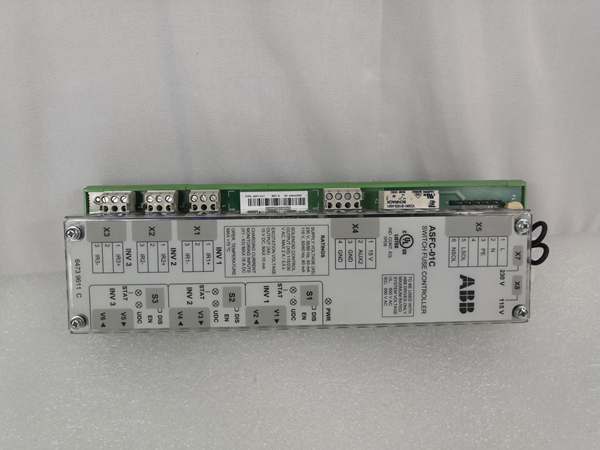
Description
Hard-Numbers: Technical Specifications
- Analog Inputs: 3 differential inputs (1 voltage: ±10V/0-10V, 12-bit; 2 current: 4-20mA, 11-bit)
- Analog Outputs: 2 current outputs (0-20mA, 10-bit resolution)
- Digital Inputs: 7 programmable inputs (24V DC, hardware filtering 1ms)
- Digital Outputs: 3 relay outputs (changeover contact, 24V DC or 115/230V AC, 2A continuous)
- Reference Voltage Output: ±10V ±0.5%, max 10mA
- Auxiliary Power Output: +24V ±10%, max 250mA
- Isolation Voltage: 500V AC (analog I/O), 4kV AC (relay outputs)
- Operating Temperature: 0°C to +60°C
- Storage Temperature: -40°C to +70°C
- Power Consumption: 250mA typical (up to 1200mA with option modules)
- Weight: 0.6 kg
- Dimensions: 200mm × 100mm × 20mm (W × H × D)
- Communication: PPCS fiber optic link to inverter/IGBT supply module

ABB RDCU-12C
The Real-World Problem It Solves
The base ACS800 drive has limited I/O—enough for simple start/终止 but not enough when you need motor temperature feedback, remote speed reference, external interlock inputs, and alarm relays all at once. The RDCU-12C plugs into the drive and gives you those extra channels without adding external terminal blocks or marshalling panels.
Where you’ll typically find it:
- Pump skids where multiple pressure transmitters feed into drive speed control
- Conveyor systems requiring start/终止 interlocks from safety gates and emergency 终止s
- Compressor stations needing motor thermistor inputs and multiple alarm relays
- Test stands with external potentiometer speed reference and analog feedback to SCADA
This card saves you panel space and wiring time—terminate local sensors directly on the drive instead of running everything to a PLC rack.
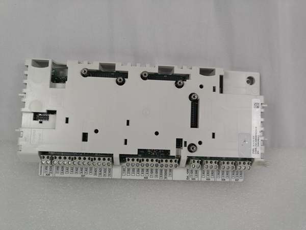
Hardware Architecture & Under-the-Hood Logic
The RDCU-12C is an intelligent I/O expansion board that communicates with the ACS800 main control processor over the PPCS (Power Plate Communication System) fiber optic link. It’s not just a dumb terminal block—it has its own processing for signal conditioning and can handle option modules in Slot 1 and Slot 2.
Internal Signal Flow:
- Analog signals from field devices arrive at terminal block X21 (differential inputs)
- Analog inputs are galvanically isolated as a group and conditioned to processor levels
- ADC converts analog signals to digital values at specified resolution (11-12 bit)
- Digital inputs at terminal block X22 are filtered with 1ms hardware time constant
- Microprocessor samples and buffers I/O data for transmission to main drive controller
- Data packets transmit via PPCS fiber optic link (V57/V68) to inverter/IGBT module
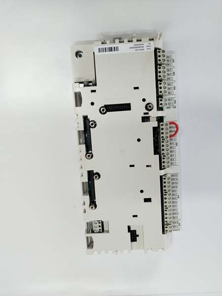
- Relay outputs X25-X27 switch based on commands from main drive controller
- Option modules (RAIO, RDIO, fieldbus adapters) in Slot 1/2 communicate via backplane
- Auxiliary power output X23 provides 24V to external devices from drive power supply
ABB RDCU-12C
Field Service Pitfalls: What Rookies Get Wrong
Forget to Load Application Software
Techs swap a failed RDCU-12C and wonder why the FAULT light blinks and the drive won’t run. The board ships blank—no firmware, no parameter set, no application software. The main drive controller doesn’t recognize it until you load the correct software via the DriveWindow tool or FlashDrop utility.
Field Rule: Always back up the application software from the failed unit before removal. Load the matching software code (AMXRxxxx, ASxRxxxx, or AHxRxxxx) into the replacement board and verify parameter set before applying power to the motor.
Ground the Analog I/O Shield Incorrectly
I’ve seen techs leave the analog input shield floating or ground both ends, creating ground loops that make your 4-20mA signals drift all over the place. The drive sees 10mA when the transmitter is putting out 12mA, and your speed control oscillates.
Quick Fix: Terminate the cable shield drain wire to the PE terminal at the RDCU-12C only. Use the shield clamp on the terminal block—don’t stuff it under a screw with the signal conductor. Ground at the drive end only, never at the sensor end, unless you have a specifically designed grounded transmitter.
Ignore the 250mA Auxiliary Power Limit
The X23 terminal provides +24V for external devices, but techs load it with a 24V relay coil and two sensor loops, drawing 400mA total. The voltage sags, your digital inputs drop below 12V threshold, and the drive thinks all interlocks are open. You chase ghost faults for hours.
Quick Fix: Calculate your external load before connecting. The aux output maxes at 250mA without option modules—less with options installed. If you need more power, use an external 24V supply and tie the grounds together at the drive cabinet. Don’t overload the onboard supply.
Mix Up Slot 1 and Slot 2 Module Types
RDCU-12C has two expansion slots, but they’re not identical—Slot 1 is for I/O extension and encoder interfaces, Slot 2 typically for fieldbus adapters. Techs shove a PROFIBUS adapter into Slot 1 and can’t figure out why the drive doesn’t see the network.
Quick Fix: Check the hardware manual for your specific option module. Slot 1 (X31) handles RAIO I/O modules and RTAC encoder cards. Slot 2 (X32) is for RPBA/RMBA fieldbus adapters. If you’re not sure, the connector keying usually prevents physical insertion in the wrong slot—don’t force it.
Skip the Fiber Optic Connector Care
The PPCS fiber link (V57/V68) is how the RDCU talks to the inverter. Techs yank cables by the fiber itself, cracking the connector or getting skin oils on the glass, and you get intermittent communication faults that look like drive problems.
Field Rule: Always grab the connector housing when unplugging fiber cables. Keep the protective dust caps on when cables are disconnected. If you get grease on the connector, clean it with 99% isopropyl alcohol—never touch the fiber end with bare fingers. The minimum bend radius is 25mm—don’t kink it around sharp cabinet corners.
Commercial Availability & Pricing Note
Please note: The listed price is for reference only and is not binding. Final pricing and terms are subject to negotiation based on current market conditions and availability.


