
Description
Hard-Numbers: Technical Specifications
- Protocol Support : RS-485 (Modbus RTU), Panel Port communication
- Port Count : 1 RS-485 port, 1 panel connector
- Baud/Data Rate : 38.4 kbps to 460.8 kbps (configurable)
- Operating Temperature : -10°C to +50°C (standard), up to +70°C (extended range reported)
- Isolation Rating : 1500V AC (typical for ABB drive communication boards)
- Power Draw : 24 VDC input, typical consumption under 15W
- Dimensions : 120 x 80 x 247 mm
- Weight : 0.5 kg to 1.12 kg (varies by source)
- Input Impedance : ≤ 250 Ω (analog signal paths)
- Humidity : Up to 95% RH (non-condensing)
- Vibration : 0.5 g (20-500 Hz)
- Certifications : CE, UL (reported)

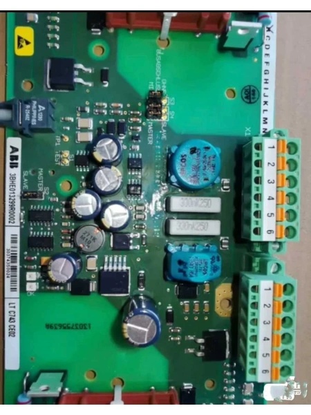
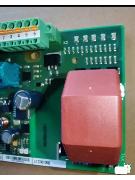
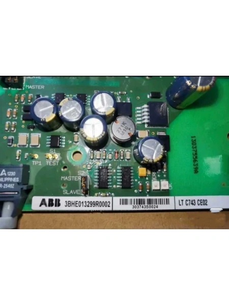
ABB LTC743CE 3BHE013299R0002
The Real-World Problem It Solves
Communication breakdowns between your drive system and external controllers kill uptime. When the red FAULT light flickers and your PLC drops off the network, it’s usually this board failing to bridge the control gap.
Where you’ll typically find it:
- Pulp and paper mills with multi-drive sectional control
- Oil and gas pump stations requiring networked drive coordination
- Mining conveyor systems with master-follower drive architectures
- Crane and hoist applications with precise speed reference needs
Bottom line: It keeps your drive talking to the rest of the automation system so you don’t lose process control when communication fails.
Hardware Architecture & Under-the-Hood Logic
This board plugs directly into the ACS880 drive’s main control unit backplane. It houses dedicated communication processors separate from the main drive CPU, handling protocol translation and signal isolation. The board carries its own microcontroller for managing serial communication streams, with optical or galvanic isolation protecting the drive core from external voltage spikes and ground loops.
- Signal Reception : External control commands enter via RS-485 port or panel connector, where the board’s transceiver converts differential signals to logic levels.
- Protocol Processing : The onboard microcontroller parses Modbus RTU frames or panel port packets, validating checksums and addressing before passing data to the drive control core.
- Signal Isolation : Galvanic isolation circuits (typically optocouplers or digital isolators) separate external communication circuitry from the drive’s internal 24V/5V logic rails, preventing ground loops and transients from reaching sensitive control electronics.
- Backplane Transfer : Processed control words and speed references pass through the backplane connector to the drive’s main CPU, where Direct Torque Control (DTC) executes motor commands.
- Status Feedback : Drive status signals, fault codes, and actual values travel the reverse path—backplane to isolation to transceiver—before being transmitted as response packets to the supervisory PLC or HMI.
ABB LTC743CE 3BHE013299R0002
Field Service Pitfalls: What Rookies Get Wrong
Improper Grounding Causes Intermittent Communication
Running RS-485 cables through cabinets without proper reference points creates ground potential differences that corrupt data packets. New engineers often daisy-chain grounds or terminate shields incorrectly, leading to random communication drops that are hell to diagnose.
Field Rule: Ground the shield at one end only—typically the drive cabinet side—and use twisted-pair cable with proper impedance matching (120 ohm terminators at both ends of the bus).
Ignoring Backplane Seating During Installation
Slamming the board into the drive cabinet without verifying proper connector alignment bends pins or creates marginal contacts. The board appears to work initially but fails under thermal cycling or vibration months later.
Quick Fix: Before powering up, verify the board sits flush with the backplane connector. If there’s resistance, don’t force it—realign and engage the locking mechanism fully. Apply torque to the mounting screws evenly to prevent board warping.
Hot-Swapping Without Checking Power States
Technicians pull boards live without confirming the drive’s control power is isolated, risking backfeeding voltage through the communication ports and frying the transceivers. Even if the drive is in standby, residual voltage on the bus can damage isolation components.
Field Rule: Verify all control power (24V DC) is off and discharge any capacitance before removing the board. If your process allows, use the drive’s maintenance mode or isolation switch rather than pulling breakers blindly.
Commercial Availability & Pricing Note
Please note: The listed price is for reference only and is not binding. Final pricing and terms are subject to negotiation based on current market conditions and availability.


