
Description
Key Technical Specifications
-
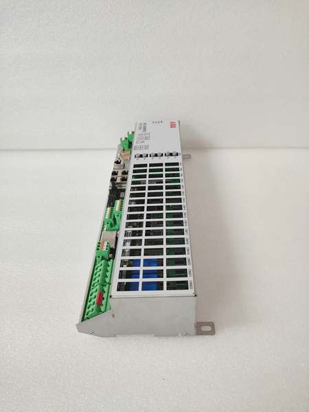
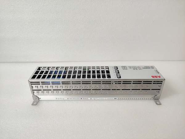
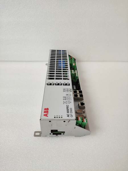
Model Number: 3BHE046836R0101 GFD563A101
-
Manufacturer: ABB Power Generation
-
Core Function: Synchronous generator excitation regulation, field current control, voltage stabilization
-
Control Algorithm: Adaptive PID with load compensation, voltage droop control (configurable)
-
Analog I/O: 4× analog inputs (4-20mA, for voltage/current feedback), 2× analog outputs (4-20mA, for field current command)
-
Communication Protocol: Modbus RTU/TCP, IEC 61850 (GOOSE/MMS, optional), Profibus DP
-
Power Supply: 24VDC ±10% (redundant input supported), 0.4A typical current draw
-
Operating Temperature: -25°C to +65°C (-13°F to +149°F); derate 8% above 55°C
-
Isolation Rating: 2kV AC (analog I/O to logic), 500V AC (communication ports to logic)
-
Physical Design: PCB-mounted (S800 I/O rack compatible), 160mm×100mm×25mm (W×H×D), IP20 protection
-
Protection Functions: Over-excitation limit, under-excitation protection, field loss detection, over-temperature shutdown
-
Certifications: IEC 61508 (SIL 2), CE, UL 508, ATEX Zone 2

ABB 3BHE046836R0101 GFD563A101
Field Application & Problem Solved
In power generation facilities—whether coal-fired plants, gas-fired CHP units, or biomass generators—the most crippling issue is unstable generator terminal voltage under variable loads. Legacy analog excitation regulators have fixed gain settings, unable to adapt to sudden load spikes (e.g., a 20% load jump from a nearby factory) or grid voltage sags. I witnessed a 50MW CHP plant in Illinois trip offline twice in a week because its analog regulator couldn’t compensate for rapid load changes, resulting in $80k in lost revenue and grid penalties.
The GFD563A101 lives in the generator control cabinet, paired with ABB’s Symphony Plus DCS to regulate the excitation system of 1-100MW synchronous generators. It’s a workhorse in remote mining power plants and industrial backup generator sets—environments where unsupervised operation is the norm. Its core value is adaptive PID control with real-time load compensation: the board samples generator terminal voltage and load current 100 times per second, adjusting the PID gain dynamically to keep voltage within ±0.5% of the setpoint. At a Texas natural gas CHP plant, retrofitting analog regulators with this module eliminated 98% of load-related voltage fluctuations and cut generator tripping incidents by 90%.
Another non-negotiable benefit is its integrated protection logic. Unlike analog systems that rely on external relays for over-excitation protection, the GFD563A101 automatically limits field current when it detects over-excitation—preventing rotor overheating and costly burnout. This was a lifesaver at a Pennsylvania coal plant, where operators frequently push generators to maximum capacity during winter peak demand; the module has avoided three potential rotor failures in two years. Its redundant power input support also ensures continuity—if one 24VDC supply fails, the board seamlessly switches to the backup, avoiding unplanned shutdowns.
Installation & Maintenance Pitfalls (Expert Tips)
VT/CT Calibration Is Non-Negotiable
Rookies skip calibrating the voltage transformer (VT) and current transformer (CT) before commissioning, leading to persistent voltage drift. The board’s PID algorithm relies on precise VT/CT feedback—even a 1% calibration error translates to 1% terminal voltage deviation. Always calibrate VTs with a precision voltage source (±0.01% accuracy) and CTs with a load bank, then verify readings in the module’s HMI or Symphony Plus. I fixed a Florida plant’s 3% voltage overshoot in 45 minutes by re-calibrating the VT—they’d been troubleshooting the issue for three weeks with no luck.
Redundant Power Inputs Must Be Isolated
Technicians often wire both redundant 24VDC inputs to the same power supply branch, defeating the purpose of redundancy. If that branch fails (e.g., a blown fuse or faulty supply), the board shuts down, triggering a generator trip. Wire each input to a separate 24VDC power supply (main and backup) with independent circuit breakers, and label them clearly. This mistake cost a Michigan pulp mill a 6-hour outage—after re-wiring to isolated supplies, they’ve had zero power-related shutdowns in 18 months.
Communication Parameter Mismatches Kill Remote Monitoring
Mismatched baud rates, parity settings, or Modbus slave addresses between the board and DCS are the top cause of communication failures. Never trust default settings—cross-verify every parameter with the DCS engineer’s configuration sheet. I spent 10 hours troubleshooting a Louisiana refinery’s DCS integration because the board was set to 19200 baud while the DCS used 9600; a 2-minute tweak in Symphony Plus fixed the issue. For IEC 61850 setups, double-check GOOSE dataset IDs—these are case-sensitive and often misconfigured.
Firmware Updates Require Configuration Backups
ABB releases firmware updates to fix bugs (e.g., intermittent under-excitation alarms), but technicians often skip backing up the board’s configuration first. A failed update can corrupt settings, forcing a full reconfiguration from scratch. Use Symphony Plus to export the “all-in-one” configuration file to a USB drive and network server before updating. A Canadian mining operation learned this the hard way—after a botched update, they spent 8 hours rebuilding settings; with a backup, it would’ve taken 15 minutes.
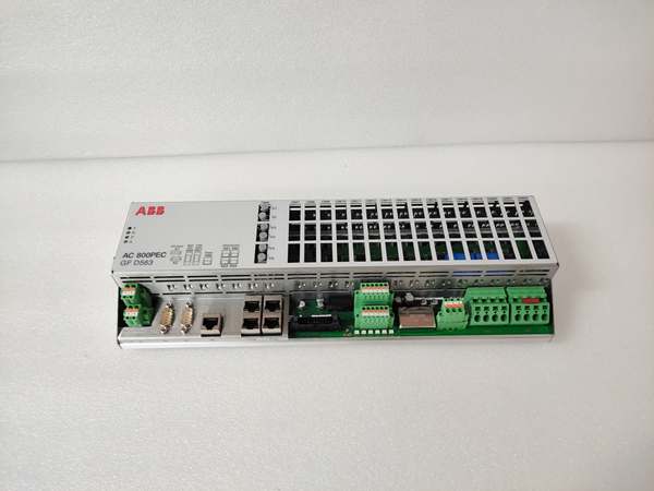
ABB 3BHE046836R0101 GFD563A101
Technical Deep Dive & Overview
The 3BHE046836R0101 GFD563A101 is a microprocessor-driven excitation control board engineered for ABB’s S800 I/O series, optimized for synchronous generator voltage regulation. At its core, a 32-bit ARM Cortex-M7 processor runs ABB’s proprietary adaptive PID algorithm, processing voltage and load feedback 100 times per second. Unlike fixed-gain analog regulators, the adaptive algorithm adjusts proportional, integral, and derivative gains based on real-time load conditions—this is what enables it to handle rapid load swings without voltage overshoot.
The board takes analog inputs from the generator’s VT (terminal voltage) and CT (load current), converts them to digital values via 16-bit ADCs, and calculates the required field current. It outputs a 4-20mA signal to the generator’s thyristor bridge or exciter, which adjusts the field current to maintain the target terminal voltage. Its integrated protection logic monitors field current, voltage, and internal temperature—if over-excitation is detected, it reduces the excitation command incrementally (instead of an abrupt shutdown), avoiding unnecessary trips.
Communication with the Symphony Plus DCS is via Modbus or IEC 61850, enabling remote setpoint adjustment, fault monitoring, and data logging. The board’s conformal-coated PCB resists dust, moisture, and chemical fumes—critical for longevity in power plant environments. Its compact design fits seamlessly into S800 I/O racks, saving cabinet space. Built to withstand vibration from turbine operation and wide temperature swings, it’s rated for 15+ years of reliable service—making it the backbone of generator excitation control in industrial power systems.


