
Description
Product Introduction
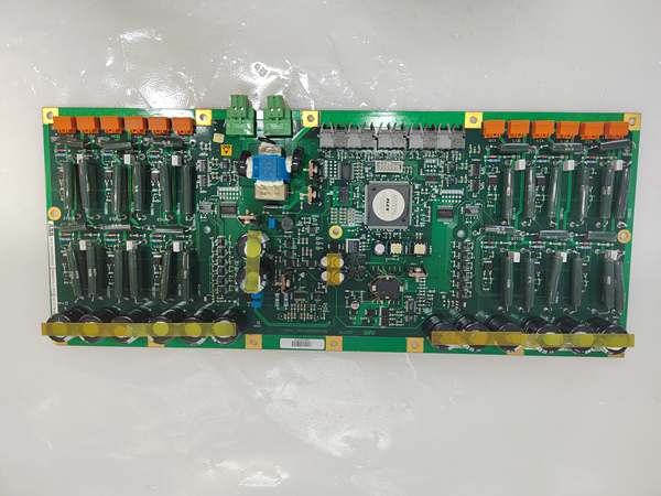
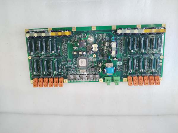
The (specifically the CE102 hardware/firmware variant) is a high-integrity Drive Control Module designed for ABB’s medium to high-power AC drive platforms, such as the ACS880, ACS600, and PCS6000 series. It serves as the “brain” of the drive, processing encoder feedback, executing Direct Torque Control (DTC) algorithms, handling PID loops, and managing communication with PLCs (via Profibus, Modbus, etc.).
This module (3BHE027859R0102) typically houses a Digital Signal Processor (DSP) or high-performance RISC CPU. It receives power from the drive’s internal 24 V DC backplane and interfaces directly with the power stack’s gate drivers (like GUSP or S-073N) via fiber optics or high-speed buses. It is programmable/configured via DriveWindow or Drive Composer software.
Key Technical Specifications
| Parameter | Value |
|---|---|
| Full Model | CE102 (3BHE027859R0102) |
| Function | Drive Controller / CPU Board |
| Compatible Drives | ACS880, ACS600, ACS800, PCS6000 (Verify specific drive manual) |
| Processor | DSP / 32-bit RISC (High-speed execution) |
| Supply Voltage | 24 V DC (Via Drive Backplane) |
| Communication | Internal Drive Bus + Fieldbus (Profibus DP, Modbus, etc.) |
| Feedback Support | Encoder (TTL/HTL), Resolver, SinCos |
| Control Features | DTC (Direct Torque Control), PID, Autotuning |
| Diagnostics | LED Status Indicators, Event Logging |
| Mounting | Internal Slot (Plug-in to Drive Control Unit) |
| Operating Temp | 0°C to +50°C / +70°C (Drive dependent) |
Quality Control Process (Engineer’s Perspective)
- Incoming Verification: Verify the laser/printed
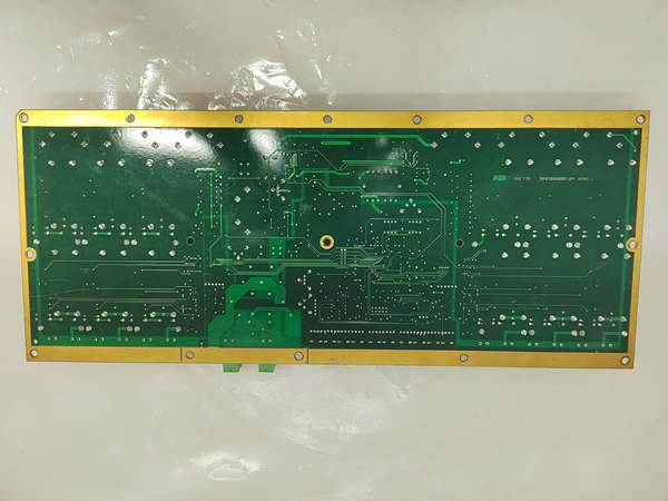
3BHE027859R0102andCE102markings on the PCB. Inspect the edge connector (gold fingers) for oxidation, burning, or socket insertion scars. Check all electrolytic capacitors for bulging (common aging point). - Visual Inspection: Look for cold solder joints around the processor and memory chips. Check the battery (if equipped for parameter backup) voltage—replace if <3.0V.
- Live Bench Test: If possible, seat in a compatible test drive/chassis. Power up and connect via DriveWindow. Check the firmware version (
CE102) and run a System Self-Test. Verify it can execute a dummy motor tuning sequence without “Par Mismatch” or “Int Err” faults. - Bus & I/O Check: Monitor the communication status with the power stack (e.g., via fiber link simulation). Ensure the module can initialize the I/O scan without dropping channels.
- Final QC & Packaging: Clean edge connectors with isopropyl alcohol. Place in ESD-safe anti-static tubing/bag with desiccant. Label “QC Passed – Firmware Verified [Version]” with the date.
Replacement Pitfall Guide
❗ The 3BHE027859R0102is specifically the variant. You generally cannot swap this with a BE01or BE02variant without checking firmware/parameter compatibility. Mismatches can cause “Incompatible HW” faults or, worse, incorrect I/O mapping (e.g., Digital Input 1 meaning something different on vs BE02).
❗ Drive Compatibility: While used in ACS880/ACS600, always cross-reference the specific drive type code (e.g., ACS880-04-590A-3). A from a 500kW drive might lack the I/O configuration for a 1MW drive, even if the part number matches.
❗ Parameter Loss: Replacing the board usually resets drive parameters to factory defaults (unless the drive has a separate parameter unit/flash). Always back up the .dcmor .prmfile via DriveWindow before swapping the board. Restoring parameters incorrectly (e.g., motor data mismatch) can cause overcurrent or mechanical damage on restart.
❗ Seating & ESD: This is a sensitive PCB. Ensure the drive is powered down (Lockout/Tagout). Discharge static to the drive chassis before handling. Firmly seat the board in the control unit slot; “half-seated” boards cause intermittent “Comm Loss” or “Control Panel Missing” errors.
❗ Fiber Optic Links: If this CPU talks to the power stack (IGCT/IGBT drivers) via fiber, ensure the Tx/Rx fibers are reinserted in the exact same ports. Swapping Ch Aand Ch Bfibers results in “Gate Fail” or “Fiber Fault” alarms.
Keep these in mind and you’ll cut 90% of rework time.
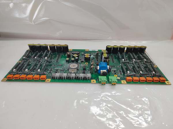
ABB DDC779 3BHE027859R0102
Compatibility Matrix & Benchmarks
- Caution — BE02 is often for MasterPiece 200/Advant OCS controllers (Process Control). The R0102 () is for Drives. Do not interchange unless the drive manual explicitly lists both as spares.
- Core Component — Plugs into the drive’s control module (e.g., RETA-01 slot or integrated CU).
- Incompatible — PPD113 is a standalone Power Electronics Controller; is a drive-embedded slave/control board.
- Control Cycle: Microsecond-level (DTC execution)
- Processor Type: DSP/RISC (Optimized for math-intensive motor models)
- Config Tool: ABB DriveWindow / Drive Composer


