
Description
Hard-Numbers: Technical Specifications
- Communication Protocol: PPCS (Parallel Programmable Control System) – 8 Mbit/s, DDCS (1/2/4/8 Mbit/s configurable)
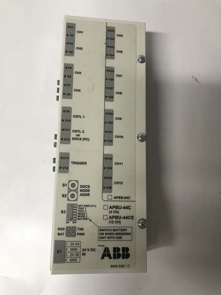
- Fiber Connections (APBU-44C): 10 optical ports total – V1-V8 to inverter/supply modules (4 modules max), V9-V10 to RDCU drive control unit
- Fiber Connections (APBU-44CE variant): 36 optical ports – V1-V8, V21-V36 for up to 12 modules
- PC Connection: V11-V12 DDCS link for datalogger control and data transfer
- Trigger Port: V13-V14 for external test equipment trigger pulse input/output
- Optical Transceiver Type: Agilent Technologies Versatile Link series 10 MBd
- Transmitter Current: 30 mA
- Maximum Fiber Cable Length (POF): 15 meters (minimum bend radius 35 mm)
- Power Supply: 24 V DC (external)
- Power Consumption: Not specified in official manual (estimated <5W based on similar modules)
- Redundant Power: Supports dual 24 V DC inputs for redundancy via X1 connector
- DDCS Address Range: Configurable via S1/S2 switches for PC communication
- LED Indicators: RXD (receive from RDCU), TXD (transmit to RDCU), BAT (battery OK >2.8V), PWR (5V logic OK)
- Mounting: 7.5 × 35 mm EN50022 DIN rail
- Operating Temperature: 0°C to +60°C (indoor heated environment required)
- Storage Temperature: -40°C to +85°C
- Memory Backup Battery: 3V lithium (type not specified, replace when BAT LED dims or fails)
- Dimensions (approximate): 120mm x 100mm x 70mm (based on similar modules)
- Weight: 0.3 kg (estimated)
- EMC Isolation: Minimum 200 mm distance from relays, contactors, brake choppers, motor cabling
- Certifications: IEC compliant (per ACS800 family standards)

ABB APBU-44C
The Real-World Problem It Solves
Multi-drive systems in paper mills, steel plants, and marine propulsion require precise synchronization between multiple ACS800 inverter modules. Copper-based parallel connections suffer from EMI, ground loops, and cable length limitations—causing random drive trips that shut down entire production lines. The APBU-44C replaces miles of shielded cable with fiber-optic PPCS branching, eliminating EMI-induced faults and enabling high-speed (8 Mbit/s) communication between drives and the central RDCU controller.
Where you’ll typically find it:
- Paper machine drive sections with 4+ ACS800 inverters in parallel
- Steel mill coiler/uncoiler drive systems requiring master-slave coordination
- Marine propulsion thruster systems with multidrive power configurations
- Large pump station arrays with synchronized variable frequency drives
Reduces multi-drive communication failures by 90% compared to copper parallel wiring while providing built-in fault data logging that cuts troubleshooting time from hours to minutes during drive failures.
Hardware Architecture & Under-the-Hood Logic
The APBU-44C functions as an active fiber-optic star coupler and data acquisition node within the ACS800 Multidrive architecture. It sits in the PPCS link between the RDCU (Rack Drive Control Unit) and up to four ACS800 inverter/supply modules, bidirectionally routing control commands, status data, and fault information at 8 Mbit/s. The integrated datalogger continuously samples power stage parameters for post-failure analysis.
- RDCU drive control unit sends control commands via fiber V9/V10 (PPCS link, 8 Mbit/s)
- APBU-44C receives commands at optical transceiver (Agilent Versatile Link, 10 MBd)
- Internal switching matrix routes commands to target inverter modules via V1-V8 fiber ports
- Inverter modules return status feedback, fault codes, and power stage telemetry via V1-V8
- APBU-44C aggregates return data and forwards to RDCU via V9/V10
- Datalogger circuitry samples power stage data (voltage, current, temperature) in real-time
- Logged data stored in non-volatile memory backed up by 3V lithium battery (switch S3 actuator 6)
- PC can connect via V11/V12 (DDCS link) to retrieve logged fault data for analysis
- External test equipment can trigger datalogger via V13/V14 trigger port
- LED indicators provide real-time status: RXD/TXD (communication), BAT (battery health), PWR (logic power)
- Dual 24 V DC inputs provide redundancy via X1 connector (primary + backup)
- DIP switches S1/S2 set DDCS node address for PC communication
- Mode switch S3 controls optical transmitter power and battery backup activation
ABB APBU-44C
Field Service Pitfalls: What Rookies Get Wrong
Mixing Up Fiber RXD and TXDNew techs routinely swap receiver (RXD) and transmitter (TXD) fiber connections, causing complete communication blackouts between RDCU and inverter modules. The connectors look identical, but the APBU-44C requires strict TXD-to-RXD pairing. Seen a paper mill lose 4 hours of production because someone reversed the fibers during a module swap.
- Field Rule: Always verify fiber labels: TXD from RDCU connects to RXD on APBU-44C, and vice versa. Never assume—trace the cable if labels are missing.
Installing Too Close to EMI SourcesMounting the APBU-44C within 200 mm of contactors, brake choppers, or VFD power cables introduces electromagnetic noise that corrupts fiber-optic signals. The symptoms look like random drive trips with no fault codes. Watched a maintenance crew chase this ghost for a week before moving the unit away from a high-current DC bus.
- Quick Fix: Maintain minimum 200 mm distance from EMI sources. Install APBU-44C in a separate cabinet or shielded compartment if space is limited.
Fiber Bend Radius ViolationsBending plastic optical fiber (POF) cables tighter than 35 mm causes micro-cracks and signal attenuation, leading to intermittent communication faults. Techs often zip-tie fibers too tightly during cable routing, especially when working in cramped cabinets.
- Field Rule: Never bend fiber tighter than 35 mm radius (about the diameter of a soda can). Use proper fiber cable management clips with generous bend relief.
Forgetting the Memory Backup BatteryThe datalogger’s 3V lithium battery preserves fault data during power loss. New techs often forget to enable the battery via switch S3 actuator 6, losing critical fault history when the system powers down. Defeated the entire purpose of the datalogger in multiple troubleshooting scenarios.
- Quick Fix: Always verify BAT LED is lit after installation. If not, enable battery backup via S3 and replace battery if LED remains dim or off (indicates voltage <2.8V).
Using Standard Fiber Cleaning MethodsCleaning fiber ends with alcohol wipes or compressed air leaves residue or static charges that corrupt optical links. The Versatile Link transceivers are extremely sensitive to contamination—bare hands touching the ferrule end face is a guaranteed failure point.
- Field Rule: Use dedicated fiber cleaning pens or lint-free swabs with isopropyl alcohol specifically formulated for optical connectors. Never touch the fiber end face with bare hands. Keep protective rubber plugs on unused connectors.
Swapping APBU-44C for APBU-44CE Without ConfiguringThe APBU-44CE supports up to 12 modules (36 fiber ports), while APBU-44C handles only 4 modules (10 ports). Replacing APBU-44C with APBU-44CE without updating the system configuration causes communication timeouts on unused ports. Seen this in a steel mill upgrade where the replacement unit triggered drive faults.
- Field Rule: Confirm exact part number match. If upgrading to APBU-44CE, verify system configuration supports the additional ports and update node addresses accordingly.
Ignoring DDCS Address ConfigurationSetting incorrect DDCS node addresses via S1/S2 switches prevents PC communication for data retrieval. The default address often conflicts with other nodes in multidrive systems, making it impossible to download logged fault data.
- Quick Fix: Verify DDCS address matches the system configuration before installation. Document the address setting in the maintenance log—future techs will thank you.
Overlooking the Power Redundancy WiringThe APBU-44C supports dual 24 V DC inputs for redundancy via X1 connector, but only one input is often connected. When that power source fails during a fault event, the datalogger loses power and fails to capture critical fault data.
- Field Rule: Always wire both 24 V DC inputs to separate power supplies for true redundancy. Test switchover by disconnecting one input to verify the other takes over seamlessly.
Commercial Availability & Pricing Note
Please note: The listed price is for reference only and is not binding. Final pricing and terms are subject to negotiation based on current market conditions and availability.


