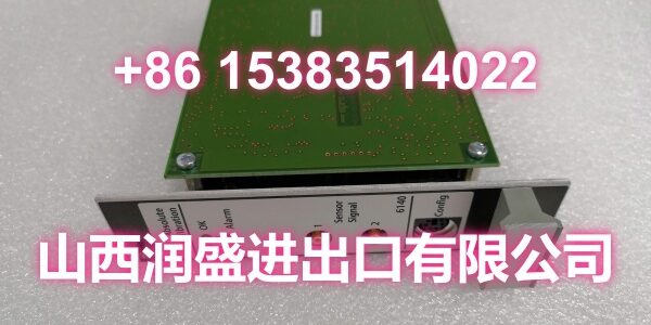
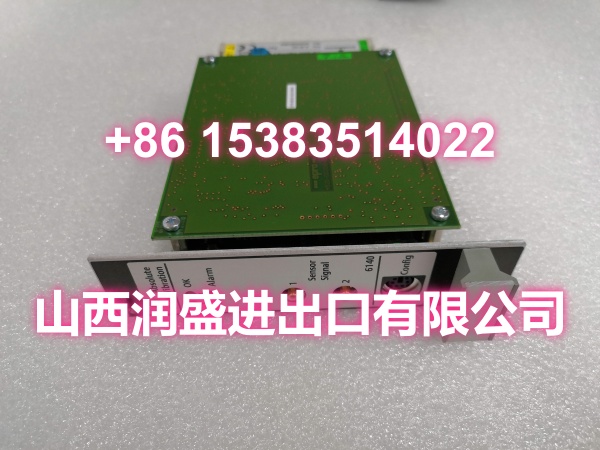
Product Core Brief
- Model: A6140
- Brand: Emerson (EPRO / AMS 6500 Series)
- Series: AMS 6500 Machinery Health Monitor
- Core Function: Dual-channel shaft absolute vibration monitor that combines eddy-current displacement sensors with seismic/piezoelectric case vibration sensors to calculate shaft absolute displacement relative to free space, providing API 670-compliant machinery protection.
- Product Type: Dual-Channel Shaft Absolute Vibration Monitor / TSI Protection Module
- Key Specs: Dual-Channel | 3U Single-Slot | API 670 Compliant | Hot-Swappable | 4-20mA Output | Self-Diagnostics | Modbus Communication
- Condition: New Original / New Surplus
Key Technical Specifications
- Module Type: Dual-Channel Shaft Absolute Vibration Monitor
- Form Factor: 3U single-slot pluggable module (half the cabinet space of traditional 4-channel 6U cards)
- Standards Compliance: API 670 compliant for machinery protection monitoring
- Hot-Swap: Supported — module can be replaced without shutting down the system
- Measurement Principle: Combines relative displacement sensor (eddy-current probe measuring shaft position relative to housing) with case vibration sensor (seismic/piezoelectric measuring housing position relative to free space); phase-compensated mathematical subtraction yields shaft absolute displacement relative to free space
- Input Channels: Two independent or combined monitoring modes
- Compatible Sensors:
- Channel 1 (Displacement): Emerson 6422, 6423, 6424, 6425 eddy-current probes with CON 011/91, 021/91, 041/91 drivers
- Channel 2 (Case Vibration): Emerson 6125 piezoelectric velocity sensor or equivalent seismic/piezoelectric sensors
- Channel 1 — Displacement Sensor Input:
- Input Resistance: >100kΩ
- Input Voltage Range: -1 to -23 VDC
- Frequency Range: Lower cutoff 1 or 5 Hz; Upper cutoff 50-2000 Hz (adjustable)
- Measurement Range: 0-400 mV p-p (smallest) to 0-2000 mV p-p (largest)
- Sensor Power Supply: -26.7 VDC nominal, 20 mA nominal / 35 mA maximum, galvanically isolated, open/short circuit proof
- Channel 2 — Case Vibration Sensor Input:
- Input Resistance: >100kΩ
- Input Voltage Range: 5 to +15 VDC
- Signal Input Voltage Range: 311-9500 mV p-p
- Frequency Range: Lower cutoff 5 or 10 Hz; Upper cutoff 50-1000 or 1600 Hz (adjustable)
- Accelerometer Supply: Constant current 0-8 mA, 30 VDC, galvanically isolated, permissible load >3.4kΩ at 8mA / >13.6kΩ at 2mA
- Outputs:
- Front and rear buffered/proportional outputs
- 0/4-20 mA analog output per channel for DCS/PLC trending
- 0-10 V output option
- Alert/Danger and OK/Fault relay contacts (rack-dependent)
- Self-Diagnostics: Monitors hardware, power input, hardware temperature, sensor status, and cable integrity
- Communication: Modbus (RTU/TCP) via rack controller/communication module
- Power Supply: 24 VDC nominal via A6xxx rack backplane; power consumption typically under 10W
- Operating Temperature: 0 to +55°C (when installed in a ventilated control cabinet)
- Dimensions: 30mm (W) × 128.4mm (H) × 160mm (D)
- Weight: Approximately 320g net / 450g with packaging
- Certifications: CE marked
Product Introduction
The Emerson A6140 is a dual-channel shaft absolute vibration monitor belonging to the AMS 6500 Machinery Health Monitor series (originally developed by EPRO, now part of Emerson). It is designed for the most critical rotating machinery in power generation, oil & gas, and process industries where shaft absolute vibration is the leading indicator of machine health.
Unlike standard relative vibration monitors that only measure shaft movement relative to the bearing housing, the A6140 calculates shaft absolute displacement relative to free space by combining two sensor inputs: an eddy-current displacement probe (measuring shaft position relative to the housing) and a seismic/piezoelectric case vibration sensor (measuring housing movement relative to free space). The module performs phase compensation and mathematical subtraction of these two signals to produce a true absolute vibration measurement. This is particularly important for sleeve-bearing machines where the bearing housing itself may move significantly during operation — when the bearing housing and rotor masses are closely matched, shaft absolute vibration is the preferred measurement for both predictive monitoring and protective tripping.
The A6140’s 3U single-slot form factor occupies half the cabinet space of traditional 4-channel 6U cards, making it ideal for retrofits and space-constrained installations. Each module provides two independent monitoring channels that can be configured for separate machines or combined for dual-sensor absolute vibration measurement on a single machine. The module is fully API 670 compliant, ensuring it meets the industry standard for machinery protection systems in critical turbomachinery applications.
Integration with plant control systems is straightforward. The A6140 provides 4-20 mA analog outputs per channel for real-time vibration trending in DCS/PLC systems, buffered dynamic outputs for portable analyzers and diagnostic tools, and Modbus communication (via the rack controller) for historian integration and CMMS connectivity. The protection logic resides locally in the rack, meaning trip decisions do not depend on network health — a critical reliability feature for safety-critical machinery.
The module includes comprehensive self-diagnostics that continuously monitor hardware health, power input quality, internal temperature, sensor status, and cable integrity. This proactive monitoring enables maintenance teams to identify degrading sensors or wiring issues before they cause false trips or loss of protection coverage. Front-panel LEDs provide at-a-glance status indication, while detailed diagnostic data is accessible via Modbus or the AMS software suite.
As part of the AMS 6500 platform, the A6140 integrates seamlessly with Emerson’s PlantWeb digital architecture and AMS Suite software, providing maintenance personnel with advanced predictive diagnostics and performance analysis tools. This enables early and accurate identification of machine faults such as imbalance, misalignment, bearing wear, and rub conditions — well before catastrophic failure occurs.
Typical applications include:
- Power generation: Steam turbines, gas turbines, boiler feedwater pumps, condensate extraction pumps
- Oil & gas: API 617/618 centrifugal and reciprocating compressors, pipeline compressors
- Refining & petrochemical: Motor-driven and steam-turbine-driven pumps, compressors, fin-fans
- Pulp & paper / metals: Process pumps, blowers, gear-driven trains
- Hydroelectric: Water turbine monitoring
The A6140 supports hot-swap replacement, allowing maintenance teams to replace a faulty module without shutting down the protected machinery — a critical feature for continuous-process facilities where unplanned downtime costs millions.
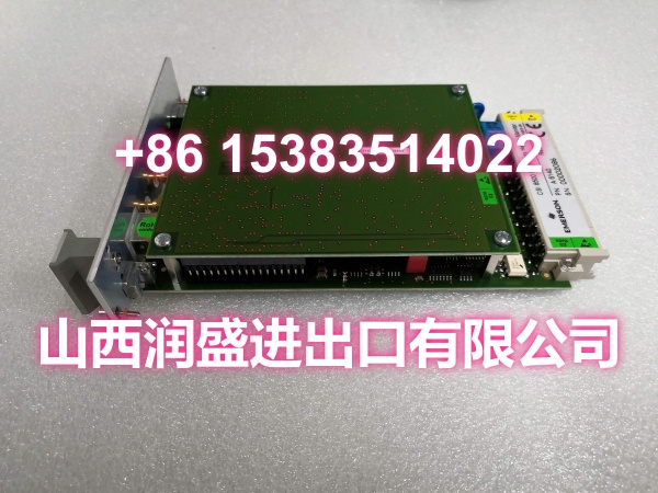
QA & Testing SOP
Vibration protection modules are safety-critical — a failure can mean either a missed trip (catastrophic machine damage) or a false trip (costly unplanned shutdown). Here’s our verification procedure:
- Visual & Anti-Counterfeit Inspection: We inspect the PCB for cold solder joints around the signal processing ICs, relay contacts, and backplane connector. We verify the OEM labeling and cross-check the part number (A6140, 9199-00058) against the AMS 6500 master parts list. Counterfeit vibration modules in the surplus market may have degraded signal conditioning circuits that produce inaccurate readings or fail to trip when needed.
- Backplane & Connector Verification: The module is seated into a dedicated A6xxx test rack. We inspect the backplane connector pins for bends or corrosion — bent pins on the data bus side cause communication failures; bent pins on the power side prevent the module from powering up.
- Power-On & Self-Test: We apply 24 VDC backplane power and verify the module completes its power-on self-test without fault codes. We confirm the OK LED is solid green and the fault LED is off. We verify the module reports no internal hardware, temperature, or power supply faults via the diagnostic interface.
- Sensor Simulation Test — Channel 1 (Displacement): We connect a simulated eddy-current probe signal to Channel 1 and verify the module correctly interprets the displacement sensor input across the full voltage range (-1 to -23 VDC). We verify the sensor power supply outputs the correct -26.7 VDC nominal voltage and can source up to 35 mA. We test open-circuit and short-circuit detection — the module should flag sensor/cable faults immediately.
- Sensor Simulation Test — Channel 2 (Case Vibration): We connect a simulated piezoelectric/seismic sensor signal to Channel 2 and verify correct interpretation across the 311-9500 mV p-p range. We verify the accelerometer constant-current supply (0-8 mA, 30 VDC) functions correctly and that the permissible load specifications are met.
- Absolute Vibration Calculation Test: We apply synchronized displacement and case vibration signals to both channels and verify the module correctly performs phase compensation and mathematical subtraction to produce the shaft absolute vibration output. We verify the calculated absolute value matches expected results across multiple test points.
- Frequency Response Test: We sweep the input signal frequency across the adjustable range (lower cutoff 1/5 Hz, upper cutoff 50-2000 Hz for Channel 1; lower cutoff 5/10 Hz, upper cutoff 50-1600 Hz for Channel 2) and verify the module’s frequency response matches specifications. We confirm the cutoff frequencies are correctly configured per the module’s setup.
- Analog Output Test: We verify the 4-20 mA (and 0-10 V) analog outputs correctly track the measured vibration values. We check output accuracy against the module’s ±2% FS specification. We verify both front and rear buffered outputs are functional.
- Relay Trip Test: We simulate vibration levels exceeding the configured Alert and Danger setpoints and verify the corresponding relay contacts activate correctly. We verify the OK/Fault relay responds to internal module faults (sensor open, power loss, hardware failure).
- Communication Test: We connect to the module via Modbus (RTU/TCP) through the rack controller and verify we can read measured values, status information, and diagnostic data. We verify the module appears correctly in the AMS software or Modbus master.
- Extended Burn-In Test: The module is operated under load for 24 hours with simulated vibration signals applied. We monitor for any drift in measurement accuracy, relay chatter, communication dropouts, or thermal issues throughout the test.
- Anti-Static Packaging: Passed units are sealed in static-shielded bags with desiccant, then double-boxed for transit.
Installation Pitfalls & Guide
Vibration protection modules require careful installation — incorrect sensor wiring or configuration can cause false trips or, worse, failure to trip during a real machine fault. Here’s what to watch for:
- ❗ Sensor Compatibility: The A6140 is designed for specific Emerson sensor combinations — Channel 1 requires eddy-current probes (6422/6423/6424/6425) with matching CON drivers (011/91, 021/91, 041/91), and Channel 2 requires a compatible piezoelectric/seismic sensor (e.g., 6125). Using non-compatible sensors will produce incorrect absolute vibration calculations. Always verify sensor part numbers against the module’s compatibility list before installation.
- ❗ Phase Compensation Configuration: The absolute vibration calculation depends on correct phase compensation between the displacement and case vibration sensors. The phase relationship must be configured correctly in the module setup — incorrect phase settings will produce erroneous absolute vibration values that could cause false trips or mask real problems. Verify phase settings during commissioning using a known reference signal.
- ❗ Cable Shielding & Grounding: Vibration signals are low-level analog signals susceptible to electromagnetic interference. Use shielded cables with proper drain-wire termination to a single-point ground. Avoid routing sensor cables near power cables, VFD outputs, or other high-noise sources. Ground loops can introduce significant measurement errors.
- ❗ Sensor Power Supply Verification: Before connecting sensors, verify the module’s sensor power supply outputs are within specification (-26.7 VDC for Channel 1, 30 VDC constant current for Channel 2). An out-of-spec power supply will cause incorrect sensor readings. Check for open-circuit and short-circuit conditions on the sensor supply — the module should detect and report these faults.
- ❗ Frequency Range Configuration: The A6140’s frequency response is adjustable (lower cutoff 1/5 Hz, upper cutoff 50-2000 Hz for Channel 1; lower cutoff 5/10 Hz, upper cutoff 50-1600 Hz for Channel 2). These settings must match the machine’s expected vibration frequency range and the API 670 requirements for the specific machine type. Incorrect frequency settings can filter out important vibration components or admit noise.
- ❗ Trip Setpoint Configuration: Alert and Danger setpoints must be configured based on the machine manufacturer’s specifications and API 670 guidelines. Setpoints that are too low cause nuisance trips; setpoints that are too high fail to protect the machine. Document all setpoint values and verify them during commissioning.
- ❗ Hot-Swap Procedure: While the A6140 supports hot-swap replacement, removing a module from a live rack temporarily removes vibration protection for the monitored channels. In redundant protection configurations, verify the redundant channel is active before removing the primary module. Never remove both channels’ protection simultaneously on a running machine.
- ❗ Rack Environment: The A6xxx rack must be installed in a clean, ventilated cabinet maintaining 0-55°C ambient temperature. Avoid mounting the rack on vibrating panel doors — external vibration can affect the module’s internal components and measurement accuracy. Ensure adequate airflow around the module for heat dissipation.
- ❗ ESD Protection: The A6140 contains sensitive analog signal processing circuits. Always wear a grounded ESD wrist strap when handling modules. Store modules in anti-static bags when not installed. ESD damage to the signal conditioning circuits may not be immediately visible but can cause measurement drift or premature failure.
4-Step Replacement Guide:
- Pre-Install: Document the current module’s configuration — channel assignments, sensor types, frequency ranges, trip setpoints, and phase compensation settings. If the existing module is still operational, read and backup all configuration data via Modbus or AMS software. Verify the replacement module is the correct part number (A6140, 9199-00058). If replacing on a running machine, confirm redundant protection is active or that a temporary protection plan is in place.
- Removal: If performing a hot-swap, verify the machine protection status and coordinate with operations. Disconnect sensor cables from the front-panel connectors — label each cable clearly (Channel 1 displacement, Channel 2 case vibration, analog outputs, relay outputs). Release the module’s locking mechanism and pull the module straight out of the A6xxx rack. Inspect the rack connector for debris or damaged pins.
- Install: Insert the replacement A6140 module into the rack slot, ensuring it seats fully and evenly. Engage the locking mechanism. Reconnect sensor cables to the correct channels — double-check Channel 1 (displacement) and Channel 2 (case vibration) assignments. Reconnect analog output and relay wiring per your documentation. Verify all cable connections are secure and shielded properly.
- Power-on & Commissioning: Apply power (if the rack was powered down) or verify the module powers up correctly (hot-swap). Confirm the OK LED is solid green and no fault LEDs are illuminated. Download or verify the configuration — channel types, sensor settings, frequency ranges, trip setpoints, and phase compensation. Verify sensor power supply voltages are within specification. Perform a functional test: apply a known test signal to each channel and verify the measured values, analog outputs, and relay responses are correct. Confirm Modbus communication is operational and the module reports correct data to the control system. Document the commissioning results and update maintenance records.
Technical FAQ
Q: What is the difference between shaft relative vibration and shaft absolute vibration? A: Shaft relative vibration measures the shaft’s movement relative to the bearing housing (using only an eddy-current proximity probe). Shaft absolute vibration measures the shaft’s movement relative to free space by combining the relative displacement measurement with a case vibration measurement (from a seismic or piezoelectric sensor mounted on the housing). Absolute vibration is the preferred measurement for sleeve-bearing machines where the housing itself moves significantly during operation — it provides a more accurate representation of the shaft’s true dynamic behavior.
Q: Can the A6140 be used for relative vibration monitoring only? A: Yes. The A6140’s two channels can be configured for independent monitoring modes. Channel 1 can be used for standard relative vibration monitoring with an eddy-current probe system, while Channel 2 can be used for case vibration monitoring with a seismic/piezoelectric sensor. The absolute vibration calculation (combining both channels) is one configuration option, not a requirement.
Q: What rack system does the A6140 require? A: The A6140 is designed for the Emerson A6xxx rack system (part of the AMS 6500 platform). It is a 3U single-slot module that plugs into the A6xxx backplane. The rack provides 24 VDC power, Modbus communication via the rack controller, and relay output capability. The A6140 is not compatible with other rack systems.
Q: How do I verify the A6140 is measuring correctly after installation? A: After installation, perform a commissioning test using a calibrated vibration signal generator or a known reference machine. Apply test signals to each channel and verify: (1) the measured values match the applied signals within ±2% FS, (2) the 4-20 mA outputs track correctly, (3) the relay contacts activate at the configured setpoints, and (4) the Modbus data matches the local display. For absolute vibration configurations, verify the phase compensation is correct by checking that the absolute value equals the expected vector sum of the displacement and case vibration signals.
Q: What is the warranty on surplus units? A: We provide a 12-month warranty from the date of delivery on both new original and new surplus stock. This covers manufacturing defects, DOA failures, and any integration issues discovered during commissioning. It does not cover damage from improper installation — such as incorrect sensor wiring, ESD damage from handling without proper grounding, configuration errors causing false trips, or damage from operating outside the specified temperature range.
Need help verifying sensor compatibility for your specific machine or configuring the phase compensation settings for absolute vibration measurement? Share your machine type, existing sensor part numbers, and current configuration, and I can help you confirm the correct setup.