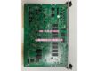
Product Core Brief
- Model: -0202-B002
- Brand: Fanuc
- Series: Fanuc CNC Control System ( Series)
- Core Function: Specialized control module designed to facilitate communication, signal processing, and data transfer within Fanuc CNC machine control systems.
- Product Type: CNC Bus Module / Control Board
- Key Specs: System Integration | Data Communication | Fanuc CNC Compatibility
- Condition: New Surplus / OEM Original
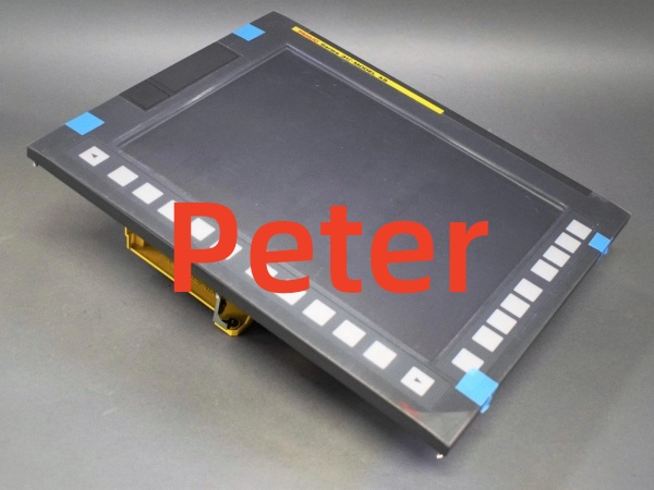
Key Technical Specifications
- Module Type: CNC Control Bus Module
- Part Number:
- System Compatibility: Fanuc CNC Control Systems
- Function: Internal system communication and bus interfacing
- Operating Environment: Standard industrial CNC cabinet conditions
- Certification: OEM Factory Standard
Product Introduction
he Fanuc is a critical internal component within the Fanuc CNC control ecosystem. As a dedicated bus module, it serves as a vital communication bridge, ensuring seamless data transfer and signal processing between the main CNC processor, I/O modules, and servo drives.
Precision manufacturing relies on flawless synchronization between the control unit and the machine’s mechanical components. This module is engineered to maintain high-speed, deterministic communication with zero latency, preventing processing bottlenecks. Built to Fanuc’s rigorous industrial standards, it guarantees long-term reliability and stable operation in demanding machine shop environments.
QA & Testing SOP
Control modules dictate the overall stability of the CNC system. We perform rigorous functional testing before release.
- Anti-Counterfeit & Visual Audit: We inspect the Fanuc silks part number, and check the PCB for physical damage, corrosion, or compromised solder joints.
- Continuity & Short Circuit Test: We perform multimeter checks on key power rails and communication buses to ensure there are no internal shorts or open circuits.
- Functional Bench Test: Where applicable, we verify the module’s ability to initialize and pass basic communication handshakes on a test bench.
- Connector Pin Inspection: We verify that all board-to-board connectors and terminal pins are straight, clean, and free of oxidation to guarantee reliable mating.
- ESD Safe Packaging: Highly sensitive microprocessors and communication ASICs are packed in anti-static shielding bags with desiccant to prevent latent semiconductor damage.
Installation Pitfalls & Guide
❗ Electrostatic Discharge (ESD) Protection: This module contains highly sensitive CMOS components. Always wear a grounded ESD wrist strap and handle the board by its edges during installation.
❗ Power Off Requirement: Never insert or remove this bus module while the CNC control unit is powered on. Always ensure the main control power and 24VDC logic power are completely disconnected.
❗ Seating and Alignment: Ensure the module is perfectly aligned with the backplane connector before applying pressure. Forcing a misaligned board can bend connector pins and cause catastrophic damage to the main backplane.
❗ Firmware/Parameter Matching: If replacing a failed module, verify that the hardware revision matches the original. Some Fanuc modules require specific parameter initialization or firmware matching after installation.
Replacement SOP:
- Pre-Install: Back up all CNC parameters, macros, and ladder logic; power down and lock out the machine.
- Removal: Disconnect any attached ribbon cables or wiring harnesses; release the module from its guide rails and extract it from the backplane.
- Install:ew into the designated slot; ensure firm and even backplane seating; reconnect all cables.
- Power-On Test: Restore power; verify the CNC boots without critical bus communication alarms; run a diagnostic test to confirm system stability.
Fanuc A13B-0202-B002
Technical FAQ
This module acts as a bus interface or communication board within the Fanuc CNC control cabinet. It facilitates internal data routing and synchronization between the main CPU and peripheral control modules.
Can I use this module in a different Fanuc control system?
Fanuc modules are often highly specific to certain control generations or cabinet configurations. Always cross-reference the exact part number with your machine’s electrical schematics or maintenance manual to ensure compatibility.
How do I know if this module is faulty?
Common symptoms of a failing bus module include intermittent CNC communication alarms, failure of specific axes or I/O to respond, or the control unit failing to boot past the initialization screen.
Why is this sold as new surplus?
This unit was pulled from sealed OEM overstock or an unfulfilled machine build project before installation. We test it electrically to verify board integrity, but we aren’t replacing internal components. You are getting unused factory hardware with original manufacturing tolerances at a fraction of the active OEM list price.