Product Core Brief
- Model: MTL5501-SR
- Brand: MTL (Eaton Crouse-Hinds)
- Series: MTL5500 Series Intrinsic Safety Isolators
- Core Function: Interfaces fail-safe switches and proximity detectors in hazardous areas with isolated electronic outputs in safe areas, featuring line fault detection.
- Product Type: Single-Channel Fail-Safe Switch/Proximity Detector Interface
- Key Specs: SIL3 Compliant (IEC 61508) | Line Fault Detection (LFD) | Solid-State Output | DIN Rail Mount
- Condition: New Original (New Surplus)
Product Introduction
The is a single-channel, fail-safe interface module designed for the most demanding safety-critical applications. It enables a fail-safe switch or proximity detector located in a hazardous area to safely control an isolated electronic output in a safe area.
Engineered to meet functional safety standards up to SIL3 according to IEC 61508, the provides comprehensive line-fault detection (LFD). If the module detects an incorrect sensor current, an open circuit, or a short circuit in the sensor loop, it automatically de-energizes the fail-safe output and triggers an LFD alarm. This robust design makes it an essential safety barrier for emergency shutdown systems and critical process monitoring in oil & gas, chemical, and power generation industries.
Key Technical Specifications
| Parameter | Value |
|---|---|
| Module Type | Fail-Safe Switch/Proximity Detector Interface |
| Safety Integrity Level | SIL3 (IEC 61508) |
| Channel Count | Single Channel |
| Input Type | NAMUR Proximity Detector / Mechanical Switch |
| Output Type | Isolated Fail-Safe Electronic Output |
| Line Fault Detection (LFD) | Open Circuit & Short Circuit Alarm |
| Power Supply | 20 to 35 Vdc |
| Mounting | 35mm T-section DIN Rail |
| Status Indicators | Yellow O/P LED, Red LFD LED |
| Certifications | IECEx, ATEX, Zone 0, SIL3 |
Quality Control Process (Engineer’s Perspective)
We don’t just box these and ship them. Here is our actual bench test workflow.
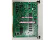
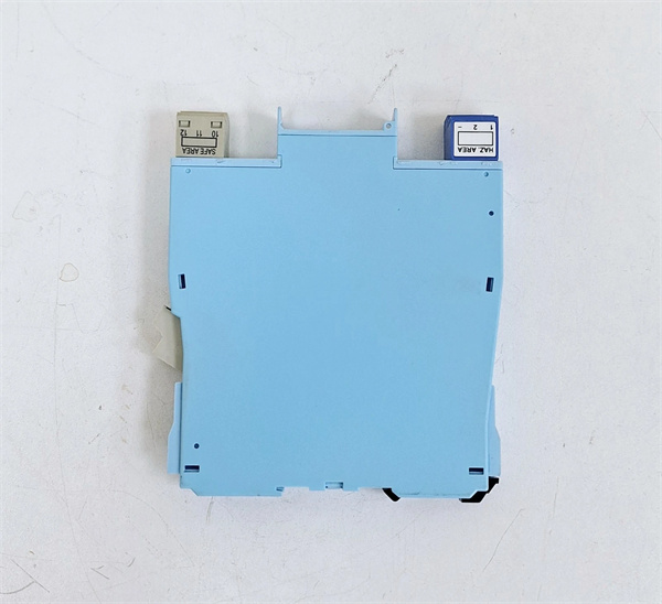
- Incoming Verification: We verify the serial number against MTL/Eaton traceability records. A visual inspection checks for physical damage, ensures the DIN rail clip is intact, and verifies the top label for correct terminal assignments.
- Live Functional Test: We mount the unit in a live test rack and apply 24 Vdc. We simulate a normal sensor current (2.9mA – 3.9mA) and verify the Yellow O/P LED illuminates and the output energizes.
- Line Fault Injection Test: We intentionally inject an open circuit (< 50µA) and a short circuit (< 100Ω) to confirm the Red LFD LED flashes and the fail-safe output immediately de-energizes.
- Electrical Parameter Test: We perform a 500 V Megger test between the hazardous-area input terminals and the safe-area output/power terminals. Insulation resistance must exceed 10 MΩ.
- Final QC & Packaging: The module is sealed in an anti-static bag with silica gel. A QC sticker showing the test date and technician initials is applied to the exterior.
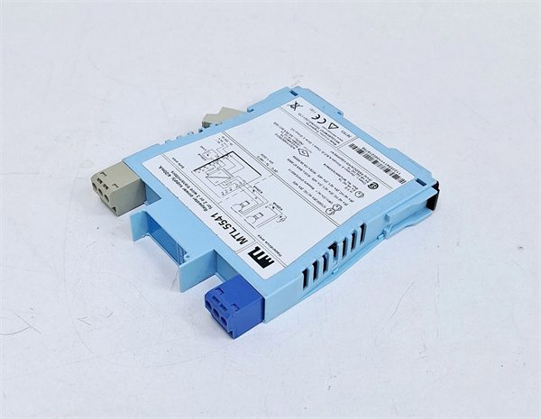
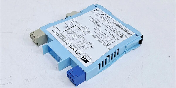
MTL MTL-5541
Replacement Pitfall Guide
Field replacements on SIL3 safety barriers are unforgiving. Watch out for these traps.
- Missing Resistors for Switch Inputs: ❗ Critical. If you are using a mechanical switch instead of a NAMUR proximity sensor, you must fit external resistors for the LFD facility to work correctly. Typically, this requires 500Ω to 1kΩ in series and 20kΩ to 25kΩ in parallel with the switch. Without these, the module cannot detect line faults.
- Sensor Compatibility: ❗ Critical. When using NAMUR proximity sensors, they must meet the “low-impedance” current requirement of 3.4 ±0.5mA. Using an incompatible sensor will cause the module to falsely trigger a line fault or fail to energize the output.
- LFD Relay Load: Ensure the load on the LFD switching relay is not less than 50mW (e.g., 10mA at 5V DC) for reliable, long-term operation.
- Terminal / Cable Incompatibility: Inspect the field wiring before connecting. A shorted switch or grounded cable will trigger the LFD circuit, mimicking a module failure. Ensure terminal screws are torqued to spec to prevent intermittent connections.
- ESD Damage: Safety barriers are sensitive to electrostatic discharge. Always wear a grounded wrist strap when handling the bare PCB. I’ve seen modules fail bench testing because they were handled on a dry winter day without protection.
Keep these in mind and you’ll cut 90% of rework time.
Compatibility Matrix & Benchmarks
Compatibility
- MTL → : Direct Replacement – Verify LFD resistor configuration for switch inputs.
- MTL MTL4501-SR → : Direct Replacement – MTL4501 is the discontinued predecessor; is the direct, plug-in compatible successor.
Benchmarks
- Fail-Safe Response: < 10 ms (from line fault detection to output de-energization)
- Normal Input Current Range: 2.9 mA < Is < 3.9 mA
Need the wiring diagram for the ? I can pull up the termination schematic showing the correct resistor configurations for mechanical switches and the NAMUR proximity detector wiring.