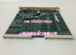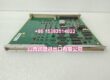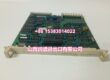
Product Core Brief
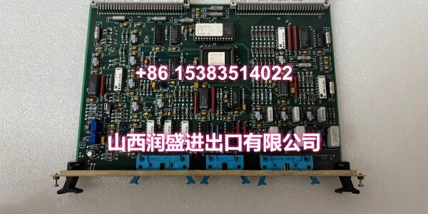
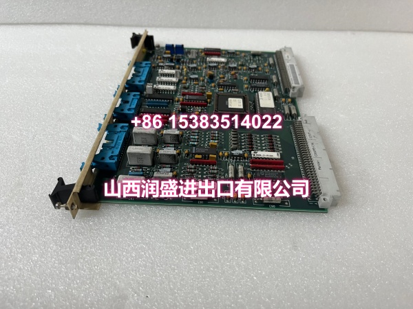
- Model: SCYC51020 (58052582H)
- Brand: ABB
- Series: ABB drive / control system pulse control board
- Core Function: Pulse control and encoder interface board; processes incremental encoder signals for speed/position feedback in ABB drive or control systems.
- Product Type: Pulse / trigger control board with encoder input
- Key Specs: Supports 15 V or 24 V encoder supply | A+, B+, Z+ encoder channels | 200 kHz max signal frequency | Isolated inputs
- Condition: New Original / New Surplus (verify by full part number)
Key Technical Specifications
- Part Number: SCYC51020 / 58052582H
- Product Type: Pulse control / trigger control board
- Encoder Supply: 15 V DC (default) or 24 V DC, selected by jumper on terminals 4–6; max 5 W
- Encoder Inputs: A+, B+, Z+ channels; isolated from logic, power, and ground
- Max Signal Frequency: 200 kHz
- Signal Levels:
- 15 V supply: “1” > 7.6 V, “0” < 5 V
- 24 V supply: “1” > 12.2 V, “0” < 8 V
- Shielding: X2 connector provides shield terminals connected to frame/ground
- Direction Logic: When the drive rotates forward, channel A should lead channel B by 90° electrical
- System Role: Typically used as a pulse/encoder interface board within ABB drive or control racks
- Lifecycle Status: Legacy component; verify current ABB lifecycle phase before long-term deployment
- Environmental: Industrial indoor cabinet installation; verify exact operating limits against the OEM nameplate
Product Introduction (No Fluff)
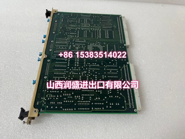
The SCYC51020 (58052582H) is an ABB pulse control board used for encoder signal processing and trigger/pulse control within ABB drive or control systems. It accepts incremental encoder signals—A+, B+, Z+—and provides selectable 15 V or 24 V encoder supply power, allowing the controller or drive to monitor speed, position, and direction.
Its practical value is maintaining reliable encoder feedback in legacy ABB installations. If the board fails or encoder signals become unstable, the drive may lose speed reference, trip on feedback fault, or run with incorrect direction. For maintenance replacements, the full number 58052582H should be matched, since jumper settings, connector layout, and firmware behavior can differ across revisions.
QA & Testing SOP (Dynamic & Transparent)
For legacy pulse/encoder boards, we verify signal path and power integrity before shipping.
- Part number verification — Confirm SCYC51020 and 58052582H on the label; check for revision mismatches.
- Visual inspection — Inspect connectors, jumpers, traces, and socketed components for corrosion, burn marks, or cracked solder joints.
- Encoder supply check — Verify the 15 V / 24 V jumper setting and measure encoder supply voltage at the terminals.
- Signal path check — Confirm A+, B+, Z+ input continuity and insulation; verify isolation between signal, power, and ground.
- Functional verification — Where test fixtures are available, apply a simulated encoder signal and verify pulse response; pack in anti-static shielding with connector protection.
Installation Pitfalls & Guide (Engineer to Engineer)
❗ Match 58052582H exactly. SCYC51020 may appear with different suffixes (e.g., 58052582/G, 58052582H). Substituting a different variant can cause jumper, connector, or signal-level mismatches.
❗ Verify encoder supply voltage. The board can supply 15 V or 24 V to the encoder depending on jumper position. Connecting a 24 V encoder to a 15 V setting—or vice versa—can cause weak signals or damage.
❗ Check A/B phase direction. Forward rotation requires channel A to lead channel B by 90°. If the motor runs in the wrong direction or the drive reports reverse feedback, swap A and B wiring.
❗ Shield the encoder cable properly. Use the shield terminals on X2 and connect the shield to the frame/ground to reduce noise on high-frequency encoder signals.
❗ Confirm system compatibility. This board is typically used in ABB drive/control applications, but the exact host unit, rack type, and mating cable should be confirmed against the existing system documentation.
Replacement steps:
- Record the existing jumper setting, cable positions, and encoder supply voltage.
- Remove power and verify zero voltage before disconnecting encoder and control cables.
- Install the replacement SCYC51020 with the same 58052582H revision and jumper configuration.
- Restore power, verify encoder supply voltage, and confirm A/B/Z signals and direction.
Technical FAQ
What does the SCYC51020 58052582H do?
It is a pulse/trigger control board that processes encoder signals—A+, B+, Z+—and provides encoder supply power for ABB drive or control systems.
Is it 15 V or 24 V?
It supports both. The encoder supply is selected by jumper: terminals 4–5 for 15 V (default), terminals 5–6 for 24 V.
Can I replace 58052582/G with 58052582H?
Not without verification. The suffix change (G → H) indicates a revision difference. While the basic function is similar, jumper defaults, connector layout, or signal conditioning may differ. Always confirm compatibility against OEM documentation or the existing system before substitution.
What encoder signals does it accept?
Incremental encoder channels A+, B+, and Z+, with a maximum signal frequency of 200 kHz.
Is it still available?
It is a legacy component. New surplus and verified replacements can be sourced, but long-term projects should evaluate migration to a supported ABB drive or control platform.