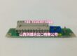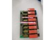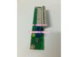
Product Core Brief
- Model: DSAI130D
- Brand: ABB
- Series: ABB Advant Master DSA Series
- Core Function: High-precision 16-channel analog input module for converting field sensor signals (temperature, pressure, flow, etc.) into digital data for DCS process control systems.
- Product Type: Analog Input Module (AI Board)
- Key Specs: 16 Input Channels | ±10V / ±10mA Input Range | 12-Bit Resolution | 0.03% Accuracy | 20ms Conversion Time | Configurable Cutoff Frequency | 24VDC Power Supply
- Note: Condition: New Original (New Surplus). Origin: Sweden/Switzerland.
Key Technical Specifications
| Parameter | Value |
|---|---|
| Manufacturer Part Number | 3BSE003127R1 |
| Device Model | |
| Device Type | Analog Input Module |
| Series | ABB Advant Master DSA Series |
| Number of Input Channels | 16 |
| Input Range | ±10V, ±10mA (configurable per channel) |
| Resolution | 12-bit (11 bits + sign for voltage; 12 unsigned bits for current) |
| Accuracy | 0.03% of span |
| Conversion Time | 20ms |
| Cutoff Frequency Options | 10Hz, 30Hz, 100Hz, 300Hz (configurable) |
| Operating Temperature Range | -20°C to +70°C |
| Storage Temperature Range | -40°C to +150°C |
| Power Supply | 24VDC |
| Communication Interface | RJ45 / FBP interface |
| Typical Applications | Temperature, pressure, flow, and level measurement in process control, chemical, oil & gas, power generation, and water treatment |
| Origin | Sweden/Switzerland |
| Condition | New Original (New Surplus) |
Product Introduction
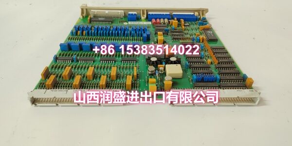
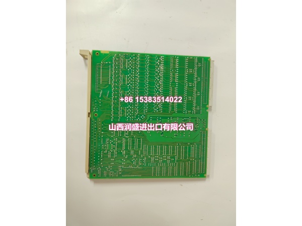
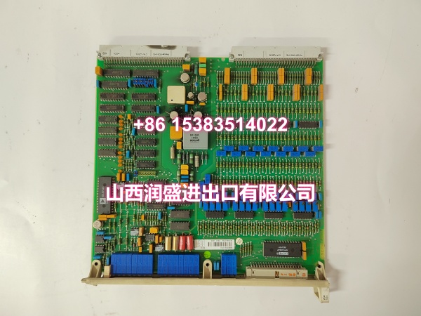
The ABB DSAI130D (order code 3BSE003127R1) is a high-precision 16-channel analog input module from ABB’s Advant Master process control system. It is designed to convert analog signals from industrial field sensors—such as temperature, pressure, flow, and level transmitters—into digital data for acquisition and processing by the upper-level DCS control system.
With 16 independent input channels supporting ±10V and ±10mA signal ranges, the DSAI130D enables high-density signal acquisition in a single module slot, reducing cabinet space requirements and wiring complexity. The 12-bit resolution (11 bits + sign for voltage signals, 12 unsigned bits for current) combined with 0.03% accuracy ensures precise measurement data for critical process control loops. The module features configurable filtering with four cutoff frequency options (10Hz, 30Hz, 100Hz, 300Hz), allowing engineers to optimize noise rejection based on the specific application environment.
The DSAI130D is built with industrial-grade components to withstand harsh operating conditions, with an operating temperature range of -20°C to +70°C. It supports hot-swappable installation, enabling module replacement without shutting down the entire control system—minimizing unplanned downtime during maintenance. The module communicates with the DCS controller via RJ45/FBP interface and integrates seamlessly with ABB Control Builder M configuration software for easy channel setup, range calibration, and diagnostic monitoring.
For engineers maintaining or upgrading legacy Advant Master installations, the DSAI130D is a direct drop-in replacement for failed or end-of-life analog input boards. Its modular design and standardized form factor ensure compatibility with existing backplane and termination unit hardware, avoiding costly mechanical rework or system redesign.
QA & Testing SOP
Every unit goes through a structured verification process before shipment:
- Visual Inspection: Check the module housing for cracks, corrosion on connector pins, and physical damage to the PCB. Verify that all channel terminal blocks are intact and undamaged.
- Connector Pin Verification: Inspect the backplane connector pins for straightness, corrosion, or bending. Bent pins cause poor contact with the backplane, leading to intermittent communication failures or channel dropouts.
- Power-On Self-Test: Apply 24VDC power and verify that the module’s status LED indicates normal operation. A red or flashing LED indicates a hardware fault or configuration error.
- Channel Accuracy Test: Where test infrastructure allows, inject a known standard signal (e.g., 4mA, 12mA, 20mA or 0V, 5V, 10V) into each channel and verify the digital output value matches the expected reading within ±0.03% accuracy tolerance. This confirms the ADC and signal conditioning circuits are functioning correctly.
- Unused Channel Configuration: Verify that any unused input channels are properly configured as “unused” in the system settings and shorted to AGND to prevent floating inputs from generating false readings or noise interference.
- Anti-Counterfeit & Packaging: Verify authenticity markings on the module body and PCB. Each unit is shipped in anti-static protective packaging with desiccant to prevent moisture absorption and connector oxidation during transit.
Installation Pitfalls & Guide
Replacing a DCS analog input module requires careful attention to electrical safety and configuration consistency.
❗ Power-Down & ESD Precautions: Always disconnect power to the rack and verify zero voltage before removing or inserting the module. Wear a properly grounded anti-static wrist strap—electrostatic discharge can damage the sensitive ADC chips and internal circuitry. Never hot-swap the module unless the system explicitly supports it and you have confirmed the backplane is designed for live insertion.
❗ Backplane Connector Alignment: When inserting the module into the backplane slot, ensure the connector pins are perfectly aligned before applying force. Forcing a misaligned module can bend pins, causing permanent damage to both the module and the backplane. Listen for the “click” that confirms the module is fully seated and locked.
❗ Unused Channel Handling: Any input channels not connected to field sensors must be configured as “unused” in the DCS configuration software and shorted to AGND (analog ground). Floating unused channels can pick up electromagnetic interference and generate false readings that may trigger spurious alarms or affect control loop stability.
❗ Signal Wiring Separation: Route signal cables separately from power cables, maintaining at least 30cm distance to prevent electromagnetic interference. Use shielded twisted-pair (STP) cables for analog signal connections, with the shield grounded at one end only (preferably at the control cabinet grounding bar).
❗ Configuration Consistency: Before replacing a failed module, document the existing channel configuration (signal type, range, filtering settings, engineering unit scaling) from the DCS configuration software. After installing the new module, verify that all channel settings match the original configuration to ensure seamless integration without control loop disruption.
4-Step Replacement Guide:
- Pre-install: Document the existing channel configuration from the DCS software. Back up the current project. Verify the replacement module’s part number (3BSE003127R1) matches the original. Prepare anti-static protection and tools.
- Removal: Disconnect power to the rack. Wear an anti-static wrist strap. Loosen the module retention screws. Gently pull the module straight out of the backplane slot. Inspect the backplane connector for damage.
- Install: Align the new module’s connector with the backplane slot. Push firmly and evenly until you hear the “click” confirming full seating. Tighten the retention screws. Reconnect power.
- Power-on Test: Apply power and verify the module’s status LED indicates normal operation. Enter the DCS diagnostic screen and confirm no hardware fault codes. Inject standard test signals into each channel and verify the HMI display values match within ±0.03% tolerance. Return to normal operation only after all channels pass verification.
Technical FAQ
1. Is the DSAI130D a communication module or an analog input module? The DSAI130D (3BSE003127R1) is an analog input module, not a communication module. Its primary function is to acquire analog signals from field sensors (voltage, current) and convert them to digital data for the DCS controller. While it does communicate with the controller via the backplane bus, its core role is signal acquisition and A/D conversion, not data routing or protocol conversion.
2. Can I substitute DSAI133A or other DSA series modules for the DSAI130D? No. Although DSAI133A, DSAI146, and other modules belong to the same DSA series and may look similar, they have different internal circuit designs, firmware versions, channel counts, and electrical specifications. Substituting a different model can cause measurement inaccuracies, configuration incompatibility, or even damage to front-end sensors. Always match the exact part number 3BSE003127R1.
3. What’s the difference between the DSAI130 and DSAI130D? The “D” suffix typically indicates a specific hardware revision or firmware version within the DSAI130 family. Different suffixes may have variations in supported signal ranges, filtering options, or communication protocols. Always verify the complete part number (including suffix) against your system’s hardware configuration before ordering a replacement.
4. How do I configure unused channels on the DSAI130D? Unused input channels should be shorted to AGND (analog ground) at the terminal block to prevent floating inputs. Additionally, these channels must be configured as “unused” in the DCS configuration software (e.g., Control Builder M) to prevent the system from attempting to read them and generating false alarms or noise-affected values.
5. What’s the difference between New Surplus and Refurbished for DCS modules? We supply this unit as New Original (New Surplus)—unused, original factory stock. This comes with a standard 12-month warranty. Refurbished DCS modules carry risks including degraded ADC performance from previous overvoltage events, worn connector pins from previous insertion cycles, and undocumented firmware version mismatches. Refurbished units typically come with 30-90 day limited warranties that don’t cover latent measurement drift or intermittent communication failures.