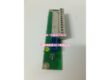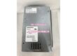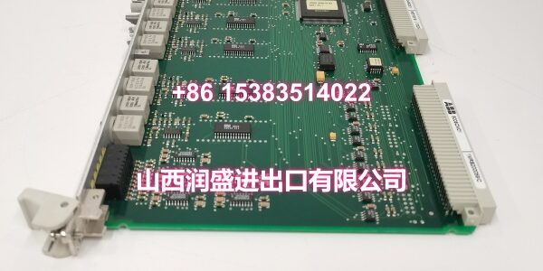
Product Core Brief
- Model: 500TTM02 / 1MB150021R01161HF930712X010
- Brand: ABB
- Series: ABB SattCon 500 PLC Platform
- Core Function: Multi-channel temperature input module for SattCon 500 systems, acquiring thermocouple/RTD signals from process equipment and converting them to digital values for PID control, alarming, and data logging.
- Product Type: Temperature Input Module
- Key Specs: Multiple isolated thermocouple/RTD input channels | High-resolution A/D conversion | Cold junction compensation | Backplane-powered | Rack-mounted installation
- Condition: New Original / New Surplus
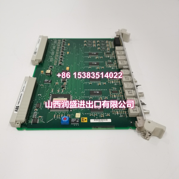
Key Technical Specifications
- Product Type: Temperature Input Module
- Brand: ABB
- Model Number: 500TTM02 / 1MB150021R01161HF930712X010
- Series: ABB SattCon 500 PLC Platform
- Input Types: Thermocouple (Type K, J, T, E, R, S, B, N — configurable per channel) and RTD (Pt100, Pt1000, Ni100 — configurable per channel)
- Channel Count: Typically 8 isolated analog input channels per module (verify against specific revision datasheet)
- Measurement Range: Thermocouple: -200°C to +1800°C (varies by type) | RTD: -200°C to +850°C
- Measurement Accuracy: Thermocouple: ±0.1°C or ±0.1% of reading (depending on range) | RTD: ±0.05°C or ±0.05% of reading
- Resolution: 16-bit A/D conversion per channel
- Sampling Rate: Up to 10 Hz per channel for real-time process monitoring
- Cold Junction Compensation: Built-in CJC for thermocouple measurements, ensuring accuracy across ambient temperature variations
- Isolation: Channel-to-channel and channel-to-backplane isolation to prevent ground loops and noise coupling in electrically harsh environments
- Power Supply: Supplied via SattCon 500 backplane — no external power supply required
- Mounting Method: Rack-mounted in SattCon 500 base; front-access screw terminals for field wiring
- Operating Temperature: 0°C to +55°C (typical for SattCon modules)
- Storage Temperature: -25°C to +70°C
- Humidity: 5% to 95% (non-condensing)
- Protection Rating: IP20 (rack-mounted, requires use inside a control cabinet)
- LED Indicators: Module status and per-channel fault LEDs for quick diagnostics
- Typical Applications: Temperature monitoring in chemical reactors, distillation columns, and heat exchangers; kiln and furnace temperature control in cement and ceramics plants; boiler tube temperature monitoring in power generation; food and beverage pasteurization/sterilization processes; HVAC and district heating network temperature acquisition
Product Introduction
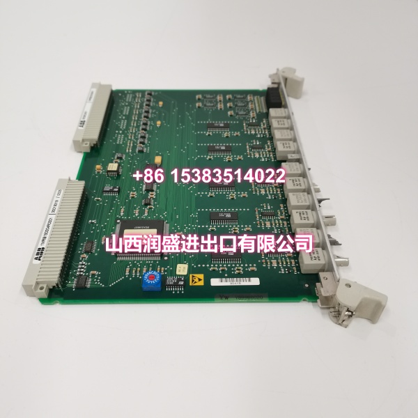
The ABB 500TTM02 (order code 1MB150021R01161HF930712X010) is a multi-channel temperature input module designed for the ABB SattCon 500 PLC platform. Its job is to acquire temperature signals from thermocouples and RTDs deployed across a process plant, convert them into high-resolution digital values, and make them available to the SattCon CPU for control logic, alarming, and historical trending.
What makes the 500TTM02 valuable for process control applications is its channel density and measurement accuracy. A single module can handle up to 8 temperature inputs, which means fewer slots consumed in the rack and lower cost per measurement point compared to single-channel transmitters. The built-in cold junction compensation ensures thermocouple readings remain accurate even when cabinet ambient temperature fluctuates — a common issue in outdoor or unconditioned control rooms. The channel-to-channel isolation prevents a ground fault on one sensor from corrupting readings on adjacent channels, which is critical in plants with large motors, VFDs, and other noise sources.
For MRO procurement teams maintaining SattCon 500 systems in aging chemical, cement, or power generation facilities, the 500TTM02 is a critical spare. Temperature measurement failures can cascade into process upsets, product quality issues, or safety incidents. Having a verified replacement module on hand means you can restore temperature monitoring quickly without waiting for long-lead OEM orders.
QA & Testing SOP
Every unit undergoes a standardized verification process before shipment:
- Visual & Anti-Counterfeit Check: Inspect the module housing for proper ABB branding, verify all identifiers (500TTM02, 1MB150021R01161HF930712X010) match the label, and check for signs of previous installation such as terminal wear, bent connector pins, or discoloration on the PCB.
- Backplane Communication Test: Insert the module into a SattCon 500 test rack and verify that the CPU recognizes the 500TTM02 correctly via the backplane bus, confirming proper firmware handshake and slot registration.
- Thermocouple Input Accuracy Test: Connect precision thermocouple simulators to each channel and apply test signals corresponding to known temperature points (e.g., 0°C, 100°C, 500°C, 1000°C for Type K). Verify that measured values fall within the specified accuracy band (±0.1°C or ±0.1%).
- RTD Input Accuracy Test: Connect precision resistance boxes simulating Pt100/Pt1000 sensors and apply test resistances corresponding to known temperature points. Verify measurement accuracy within ±0.05°C or ±0.05%.
- Cold Junction Compensation Test: Vary the ambient temperature around the module’s terminal block and verify that the CJC circuit correctly compensates, maintaining thermocouple reading accuracy.
- Channel Isolation Test: Apply a voltage differential between adjacent channels and verify that isolation resistance meets specification, confirming no crosstalk or ground loop paths.
- Open Sensor Detection Test: Disconnect input wiring on each channel and verify that the module correctly reports an open-sensor fault condition via the backplane and LED indicators.
- LED Indicator Verification: Confirm that status LEDs respond correctly to various operational states (normal operation, channel fault, module fault, communication error).
- Anti-Static Packaging: After passing all tests, the module is placed in anti-static shielding bags with desiccant packs and rigid cardboard protection for safe transit.
Installation Pitfalls & Guide
Real-World Risks When Replacing This Module:
❗ Wrong Thermocouple Type Configuration: Each channel must be configured for the correct thermocouple type (K, J, T, etc.). If a Type K thermocouple is connected but the channel is configured for Type J, the temperature reading will be significantly wrong — potentially by hundreds of degrees. Always verify the channel configuration in the PLC program matches the physical sensor type before commissioning.
❗ Missing Cold Junction Compensation Reference: The CJC circuit measures the temperature at the module’s terminal block. If the terminal block is exposed to direct sunlight, heat from adjacent equipment, or drafts from an open cabinet door, the CJC reading will be inaccurate and all thermocouple measurements on that module will drift. Ensure the module is mounted in a thermally stable location inside the cabinet.
❗ RTD Wiring Configuration Error: RTDs can be wired in 2-wire, 3-wire, or 4-wire configurations. The 3-wire configuration is most common and compensates for lead wire resistance. If a 3-wire RTD is wired as 2-wire, the reading will include the lead resistance and be artificially high. Verify the wiring configuration matches the channel setting in the PLC program.
❗ Ground Loop Through Sensor Wiring: In electrically noisy environments, unshielded thermocouple extension wire can pick up induced voltages that corrupt temperature readings. Use shielded thermocouple extension wire with the shield grounded at the cabinet end only. For RTDs, use shielded twisted-pair cable.
❗ Exceeding Channel Count Per Module: Each 500TTM02 has a fixed number of input channels (typically 8). Attempting to wire more sensors than available channels will result in unmonitored points. Plan your I/O allocation carefully and add additional modules if needed.
4-Step Replacement Guide:
- Pre-Install: Power down the SattCon 500 rack or isolate the I/O section if hot-swap is not supported. Document the existing field wiring, noting which sensor connects to which terminal on the old module. Back up the current PLC program and I/O configuration from the engineering station.
- Removal: Disconnect all field wiring from the module’s front-panel terminals. Label each wire with its channel number and sensor tag for reconnection. Release the module locking mechanism and carefully slide the old module straight out of the SattCon 500 rack. Inspect the rack connector for bent pins or debris.
- Install: Align the new 500TTM02 with the rack guides and slide it firmly into place until it locks. Reconnect the field wiring according to your documented terminal assignments. For thermocouples, verify correct polarity (positive/negative). For RTDs, verify the correct wire configuration (2/3/4-wire).
- Power-On Test: Restore rack power and verify that the CPU recognizes the module. Download the I/O configuration if needed. Verify that status LEDs indicate normal operation. Test each channel by applying a known temperature (or using a simulator) and confirming the reading in the PLC program matches the expected value. For channels reporting open-sensor faults, verify that the fault clears once a valid sensor is connected.
Technical FAQ
What thermocouple types does this module support? The 500TTM02 typically supports the most common thermocouple types: K, J, T, E, R, S, B, and N. Each channel can be individually configured for the sensor type in the PLC program. Verify the specific supported types against your module’s revision datasheet, as support can vary between hardware revisions.
Can I mix thermocouple and RTD sensors on the same module? Yes, in most SattCon 500 temperature module configurations, each channel can be independently configured for either thermocouple or RTD input. This gives you flexibility to use the most appropriate sensor type for each measurement point without dedicating separate modules to each sensor type.
What is cold junction compensation and why does it matter? Thermocouples measure the temperature difference between the measurement junction (at the sensor tip) and the reference junction (at the module’s terminal block). The CJC circuit measures the terminal block temperature and adds it to the thermocouple voltage reading to calculate the true process temperature. Without accurate CJC, thermocouple readings will drift as cabinet ambient temperature changes.
How do I troubleshoot a channel that reads incorrectly? First, verify the channel configuration in the PLC program matches the physical sensor type (thermocouple type or RTD wiring configuration). Second, check the field wiring for correct polarity (thermocouples) or proper 3/4-wire connections (RTDs). Third, measure the sensor resistance or millivolt output at the module terminals with a multimeter to confirm the sensor itself is functioning. Fourth, swap the sensor to a different channel to isolate whether the problem is with the sensor/wiring or the module channel itself.
What symptoms indicate this temperature module is failing? Common symptoms include: erratic or drifting temperature readings on one or more channels, channels reporting open-sensor faults when sensors are connected, the module status LED showing a fault condition, or the CPU reporting communication errors with the module. However, these symptoms can also be caused by sensor failures, wiring issues, or configuration errors. Always rule out field-side problems before concluding the module is at fault.
What warranty do you offer on New Surplus parts? We provide a full 12-month warranty on all New Original / New Surplus units. This is fundamentally different from refurbished temperature modules, which often carry 30–90 day warranties and come with unknown thermal cycling history, degraded A/D converters, and weakened isolation barriers. For a temperature input module that feeds critical process data to your control system, the reliability difference between new surplus and refurbished directly impacts measurement accuracy and process safety.