
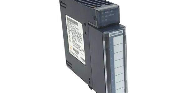
Product Core Brief
- Model:
- Brand: GE Fanuc / GE
- Series: Series 90-30 PLC
- Core Function: Intelligent 2-axis Motion Mate Axis Positioning Module (APM), executing standalone motion trajectories, closed-loop position control and electronic gearing for servo drives. Offloads motion calculations from the main CPU.
- Product Type: Dual-Axis Intelligent Motion Control Module
- Key Specs: Independent 2-axis control | Standard / Follower (Electronic Gear) mode | Incremental encoder feedback Note: Discontinued legacy hardware; factory new stock exhausted, surplus and refurbished units widely traded. The -P suffix represents specific PCB hardware revision. Hot swapping is not supported on Series 90-30 backplanes.
Key Technical Specifications
- Axis Configuration: 2 fully independent motion axes
- Operating Modes: Standard Position/Velocity mode; Follower (Electronic Gear) synchronization mode
- Supported Feedback: Differential incremental encoders
- Motion Functions: Point-to-point positioning, velocity profiling, homing, limit switch handling, cam profiling
- Trajectory Generation: Onboard processor handles acceleration/deceleration profiles independent of CPU scan
- Backplane Power Draw: 340 mA @5 VDC
- Front Panel Indicators: OK, CFG, STAT, EN1, EN2 status LEDs
- External Interface: Two high-density D-Sub connectors for drive signals, encoder feedback, home and limit inputs
- Maximum Pulse Rate: Compatible with industry standard differential servo drive interfaces
- Isolation: Field I/O galvanically isolated from PLC backplane
- Operating Temperature: 0°C to 60°C horizontal cabinet mounting
- Storage Temperature: -40°C to 85°C
- Form Factor: Single-width Series 90-30 rack slot
- Compatible Chassis: IC693CHS391, IC693CHS392, IC693CHS397, IC693CHS398
- Minimum CPU Requirement: IC693CPU311 or newer Series 90-30 CPU
- Supported Software: Logicmaster 90, Proficy Machine Edition
Product Introduction
This unit is a dedicated motion coprocessor for Series 90-30 control systems. It executes complex motion profiles locally without burdening the main PLC CPU. Two axes can operate independently or be synchronized via electronic gearing for printing, cutting, winding and packaging machinery.
All motion parameters, homing sequences and gear ratios are configured in programming software. The module exchanges command setpoints and actual position data with the CPU over the backplane. It is widely deployed on retrofit machines requiring coordinated multi-axis servo control.
QA & Testing SOP (Transparency Building)
- Incoming Inspection: Verify part marking and -P revision suffix. Inspect backplane edge pins for bending or corrosion; examine D-Sub motion connectors and housing for physical damage.
- Live Testing: Mount into validated Series 90-30 rack, apply rack power. Download motion configuration, simulate encoder feedback and verify axis trajectory execution over a continuous 24-hour test cycle.
- Electrical Testing: Use Fluke 115 to monitor backplane 5VDC rail stability. Insulation resistance testing must exceed 10MΩ between field terminals and chassis protective ground.
- Firmware/Config Backup: Record onboard module firmware version. Photograph front panel labels and connector pin layout before erasing resident motion programs.
- Final QC & Packaging: Place unit inside anti-static shielding. Attach dated QC test tag confirming motion profile execution and encoder interface validation prior to shipment.
Installation Pitfalls & Guide (Engineer to Engineer)
❗ No Hot Swap Support: Series 90-30 backplanes lack hot-swap bus logic. Live removal disrupts all rack operation and risks permanent backplane trace damage. Full rack power shutdown mandatory. ❗ Revision Suffix Matching: IC693APU302 and are mechanically interchangeable, but always perform full motion validation after cross-revision replacement to avoid minor timing differences. ❗ D-Sub Wiring Risk: Servo encoder and command wiring uses proprietary pinout. Generic cables will cause loss of feedback or axis runaway. Use validated GE motion cables. ❗ Follower Mode Timing Boundary: Master signal jitter can degrade electronic gear synchronization. Route encoder wiring separately from power cables to reduce noise. ❗ ESD Dangers: Un-grounded handling damages encoder receivers and motion logic circuits. Static faults manifest as position drift or intermittent axis faults after commissioning. ❗ Power Budget Oversight: Include the module’s 340mA 5VDC load when calculating total rack power consumption to avoid PSU overload.
Replacement Guide:
- Pre-install: Activate lockout-tagout on rack power; back up full hardware configuration and motion programs. Photograph all motion D-Sub wiring connections.
- Removal: Unplug motion cables, unlatch module and slide straight out without twisting backplane connectors.
- Install: Seat new unit fully into vacant slot, lock latches, reconnect D-Sub motion cabling.
- Power-on Test: Restore rack power, confirm OK LED status, download saved motion configuration, execute homing and positioning cycles and verify no axis fault alarms.
FAQ (Frequently Asked Questions)
Q: Does this module support hot swapping? A: No. Series 90-30 architecture does not implement hot-swap functionality. Complete rack power shutdown is required before removing or installing the unit.
Q: What is the difference between IC693APU302 and ? A: Base catalog number shares identical motion functionality. The -P suffix designates a specific PCB hardware revision. Mechanically plug-compatible, always run full motion cycle verification after substitution.
Q: Can this module be installed inside PACSystem RX3i racks? A: No. Form factor, backplane signaling and firmware are exclusive to Series 90-30 chassis. It cannot operate within RX3i systems.
Q: Does this module support stepper drives? A: It interfaces with differential pulse/direction servo drives. Direct stepper compatibility depends on drive signal interface; signal conditioning may be required.
Q: Can axes run in independent mode while one axis operates as follower? A: Yes. One axis may follow an external master encoder while the second axis executes independent positioning profiles.
Q: Will saved motion configuration download directly onto a replacement unit? A: Motion program logic imports without modification. Homing offsets, gear ratios and fault thresholds should be verified after replacement. Always execute full machine homing sequence.




