
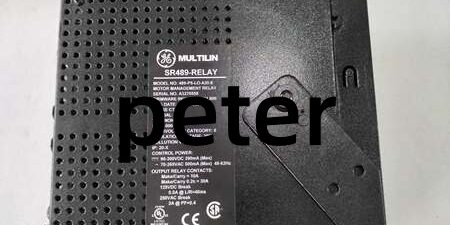
Product Core Brief
- Model: SR489-P5-LO-A20-E
- Brand: GE (Multilin / GE Vernova)
- Series: SR489 Medium/Low Capacity Synchronous Generator Protection Platform
- Core Function: Multi-function digital relay delivering full stator/rotor protection, metering, thermal monitoring, and SCADA communication for industrial synchronous generators
- Product Type: Drawout panel-mount generator management protection relay
- Key Specs: P5 = 5 A CT secondary inputs | LO = Loss of Excitation native logic | A20 = 4 isolated 4–20 mA analog outputs ⚠️ EOL — limited stock remaining
Product Introduction
GE samples PT voltage and CT current signals, executes over 30 programmable protection algorithms, and converts operational metrics to analog 4–20 mA signals for DCS plant control systems. It integrates 12-channel RTD temperature monitoring for stator and bearing thermal supervision without external I/O modules. This unit differs from the SR489-P5-HI-A20-E variant by removing high-impedance ground fault logic and optimizing firmware for small-to-medium generator setups (up to 50 MVA). It holds ±0.5 % steady-state voltage metering accuracy across -40 °C to +60 °C cabinet operating ranges, stores 256 timestamped fault event logs, and captures oscillography waveforms at 12 samples per cycle during fault transients.
Key Technical Specifications
| Parameter | Value |
|---|---|
| Secondary CT rated input | 5 A AC phase current (P5 suffix configuration) |
| Auxiliary supply voltage range | 24–60 V DC SELV; 20–48 V AC 48–62 Hz |
| Supported generator frequency | 25 Hz, 50 Hz, 60 Hz user-selectable |
| Integrated analog outputs | 4 galvanically isolated 4–20 mA (A20 suffix) |
| RTD temperature input capacity | 12 PT100/1000 stator/bearing temperature loops |
| Binary digital inputs | 8 dry-contact assignable status inputs |
| Relay output allocation | 6 independent Form-C SPDT trip/alarm contacts |
| Core native protection element | Loss of Excitation (LO suffix impedance-based logic) |
| Fault event storage capacity | 256 timestamped sequence-of-events records |
| Oscillography capture buffer | 128 cycle waveform storage at 12 samples/cycle |
| Communication ports | Dual rear RS485 (Modbus RTU / DNP3.0), front RS232 local service |
| Operating cabinet temperature | -40 °C to +60 °C sealed enclosure |
| Storage temperature range | -40 °C to +85 °C |
| Mechanical form factor | Standard 5U vertical panel cutout drawout housing |
| Net unit weight | 7.7 kg |
| Compliance standards | IEC 60034-1, IEC 60255, UL 508, CE industrial certification |
Quality Control Process (Engineer’s Perspective)
- Incoming Verification: Cross-reference serial numbers against GE Multilin generator protection spare database to flag counterfeit hardware. Inspect power terminal blocks, RS485 communication ports, and front LCD HMI with a 10x magnifier for pin corrosion or cracked housing; log serial numbers for power plant traceability.
- Live Functional Test: Mount the unit on a panel test rack paired with PT/CT signal simulators and resistive RTD load banks. Inject full-range voltage/current signals, run continuous 26-hour load testing while logging cabinet temperature shifts and recording protection element pickup timing deviation.
- Electrical Parameter Test: Use a 500 V Megger to measure insulation resistance between CT/PT high-potential terminals and chassis ground; pass threshold set at >10 MΩ. Verify PE protective ground loop resistance below 0.5 Ω with a Fluke 115 multimeter.
- Firmware Verification: Extract and record internal DSP protection firmware revision printed on PCB silkscreen. Photograph RS485 bus termination jumper and RTD input polarity labels for field commissioning reference.
- Final QC & Packaging: Wipe front HMI and metal drawout housing with anti-static microfiber cloth, cap all signal and communication ports with plastic dust covers. Seal inside a shielding ESD bag, attach a QC Passed label stamped with full test completion date.
Replacement Pitfall Guide
❗ Firmware Mismatch: firmware v5.4 drops backward compatibility with legacy Enervista 489PC software v3.0 and older. Match exact firmware builds before rack power-up, or loss of excitation protection elements will fail to pickup field impedance faults indefinitely. ❗ DIP Switch / Jumper Misconfiguration: Factory default RS485 bus termination resistor is disabled. Most multi-generator substation SCADA trunks require the resistor enabled on the last relay in the communication chain; missed settings create cyclic Modbus RTU packet loss under peak generator load. ❗ Terminal / Cable Incompatibility: This unit uses 2.5 mm spring CT/PT signal terminals, unlike UR8NH heavy-duty 2.5 mm blocks with integrated CT shorting bars. Oversized wire strands create loose measuring wiring and intermittent metering dropout; shield drain wires must land on dedicated protective ground bars only. (Always short CT secondary terminals before disconnecting wiring per GE service manual.) ❗ Power Supply Mismatch: Full auxiliary and I/O load draws 40 W peak power. Calculate rack power budget with 20 % overhead; undersized URRHH DC power supplies trigger low-voltage lockout and zero analog output readings sent to DCS panels. ❗ ESD Damage: Dry cabinet environments above 40 % relative static risk degrade internal DSP and analog output driver chips on the unit. Always use an anti-static mat and grounded wrist strap when accessing exposed rear terminal wiring and PCB edge connectors. Keep these in mind and you’ll cut 90% of rework time.
Compatibility Matrix & Benchmarks
Compatibility Matrix
- SR489-P5-HI-A20-E → : Needs Adaptation — HI variant includes high-impedance ground fault logic, loss of excitation parameters require re-tuning
- UR9HH CPU Relay → : Incompatible — separate UR series backplane architecture, no shared signal bus mapping
- UR8LH Analog Input Module → : Needs Adaptation — external transducer wiring pinout differs, analog output scaling must be reconfigured
- Multilin 889 → : Direct — functional replacement, panel cutout dimensions match, full firmware parameter export/import support




