
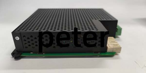
Product Core Brief
- Model: UR6CH
- Brand: GE (Multilin / GE Vernova)
- Series: UR Universal Relay Modular Digital I/O Platform
- Core Function: Process binary status inputs and drive Form-C relay outputs for substation auxiliary equipment interlock control
- Product Type: Horizontal slot rack-mounted digital input/output PCB
- Key Specs: 8 SPDT Form-C outputs | 8 binary digital inputs | 2000 V field-to-backplane isolation ⚠️ EOL — limited stock remaining
Product Introduction
GE polls binary contact signals from breakers, disconnect switches, and auxiliary trip relays, converting states to backplane data and switching isolated Form-C outputs for external control circuits. This unit differs from analog UR8LH by eliminating transducer signal circuits and adding latching-capable relay outputs. It captures timestamped SOE events with 1 ms resolution across -40 °C to +70 °C cabinet operating bands and cuts required chassis slot space by 30% vs dual-slot I/O assemblies.
Key Technical Specifications
| Parameter | Value |
|---|---|
| Digital input count | 8 dry-contact binary status channels |
| Digital output count | 8 independent SPDT Form-C relay changeover contacts |
| Field-to-backplane isolation rating | 2000 V AC reinforced galvanic separation |
| Relay contact rating | 1 A at 250 V AC / 300 V DC resistive load |
| Contact actuation response time | ≤4 ms full switch cycle |
| Auxiliary power source | UR chassis 24 V DC SELV backplane rail |
| Maximum continuous power consumption | 10 W peak full output load |
| Event logging resolution | 1 ms timestamped SOE contact change records |
| Hot-swap support | Yes; suppresses output chatter during insertion/removal |
| Operating cabinet temperature | -40 °C to +70 °C |
| Storage temperature range | -40 °C to +85 °C |
| Mechanical form factor | Single-width horizontal UR chassis slot |
| Net unit weight | 1.15 kg |
| Compliance standards | IEC 61000-6-2, UL 61010, CE industrial certification |
Quality Control Process (Engineer’s Perspective)
- Incoming Verification: Cross-reference serial numbers against GE Multilin UR spare asset database to flag counterfeit hardware. Inspect front spring terminal blocks and backplane gold edge pins with a 10x magnifier for oxidation or cracked PCB traces; log serial numbers for transmission substation traceability.
- Live Functional Test: Mount the unit on a UR test rack paired with a UR9HH CPU and dry-contact signal simulators. Toggle all 8 input channels and cycle each Form-C output relay continuously for 26 hours while logging cabinet temperature shifts and contact resistance drift.
- Electrical Parameter Test: Use a 500 V Megger to measure insulation resistance between each I/O channel and chassis ground; pass threshold set at >10 MΩ. Verify PE protective ground loop resistance below 0.5 Ω with a Fluke 115 multimeter.
- Firmware Verification: Record onboard digital logic firmware revision printed on PCB silkscreen. Photograph backplane bus termination jumper and contact wetting jumper positions for field commissioning reference.
- Final QC & Packaging: Wipe the unit plastic housing with anti-static microfiber cloth, cap all signal terminal blocks with plastic dust covers. Seal inside a shielding ESD bag, attach a QC Passed label stamped with full test completion date.
Replacement Pitfall Guide
❗ Firmware Mismatch: firmware v2.2 drops backward compatibility with UR9HH CPUs running v7.0 or older build code. Match exact firmware builds before rack power-up, or all binary input readings will lock as unchanging indefinitely. ❗ DIP Switch / Jumper Misconfiguration: Factory default backplane bus termination resistor is disabled. Most multi-module substation racks require the resistor enabled on the last I/O card in the slot chain; missed settings create cyclic backplane packet loss under full 16-point I/O load. ❗ Terminal / Cable Incompatibility: This unit uses 2.5 mm spring signal terminals, unlike low-signal UR8LH 1.5 mm blocks. Oversized wire strands create loose breaker status wiring and intermittent contact dropout; shield drain wires must land on dedicated protective ground bars only. ❗ Power Supply Mismatch: Full 8-relay output load draws 10 W peak backplane power. Calculate rack power budget with 20 % overhead; undersized URRHH power supplies trigger low-voltage lockout and zero relay switching capability. ❗ ESD Damage: Dry cabinet environments above 40 % relative static risk degrade internal relay driver chips on the unit. Always use an anti-static mat and grounded wrist strap when handling exposed PCB edge connectors and terminal pins. Keep these in mind and you’ll cut 90% of rework time.
Compatibility Matrix & Benchmarks
Compatibility Matrix
- UR8LH → : Needs Adaptation — UR8LH processes 4–20 mA analog signals, terminal pinout and backplane data mapping differ
- UR9HH Protection Relay CPU → : Direct — identical chassis backplane communication, minor SOE logging parameter adjustment required
- URRHH Power Supply → : Direct — shares standard UR chassis 24 V backplane power rails, no rack modification needed
- V7768-312000 VME SBC → : Incompatible — separate VME64 backplane architecture, no shared signal bus mapping




