
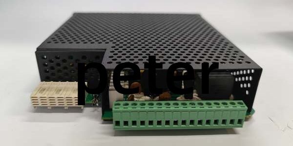
Product Core Brief
- Model: URSHA
- Brand: GE (Multilin)
- Series: UR Universal Relay Modular Power Supply Platform
- Core Function: Convert wide-range AC/DC auxiliary input to regulated 48 V DC power for UR relay CPU and dry contact I/O loops
- Product Type: DIN rail mounted chassis power supply module
- Key Specs: 120–240 V AC primary input | 48 V DC isolated I/O output | 125 W peak power draw ⚠️ EOL — limited stock remaining
Product Introduction
GE URSHA accepts high-voltage substation AC/DC auxiliary power and delivers noise-filtered 48 V DC to UR series protection relays, eliminating external signal power bricks from panel layouts. This unit differs from low-power URRHH variants by supporting 240 V AC line inputs and doubling peak power capacity to 125 W. It maintains ±1 % output voltage regulation across -20 °C to +60 °C cabinet operating bands and suppresses switching noise via dual-layer internal shielding.
Key Technical Specifications
| Parameter | Value |
|---|---|
| Primary input voltage range | 120–240 V AC single-phase; 180–300 V DC |
| Regulated secondary output | 48 V DC SELV isolated power for relay I/O |
| Maximum continuous power rating | 125 W peak load at 55 °C ambient |
| Output voltage regulation tolerance | ±1 % full scale across rated temp range |
| EMI suppression construction | Inner aluminum foil + outer copper braid shielding |
| Minimum operating airflow | 150 LFM forced cabinet cooling (verify with OEM datasheet) |
| Operating cabinet temperature | -20 °C to +60 °C |
| Storage temperature range | -40 °C to +85 °C |
| Mechanical mounting standard | EN 50022 35 mm DIN rail clip-in housing |
| Net unit weight | 0.62 kg |
| Compliance standards | IEC 61000-6-2, UL 61010, CE certified |
Quality Control Process (Engineer’s Perspective)
- Incoming Verification: Cross-reference serial numbers against GE Multilin UR spare asset database to flag counterfeit hardware. Inspect AC input terminal blocks and front power status LED with a 10x magnifier for pin oxidation or cracked housing; log serial numbers for substation traceability.
- Live Functional Test: Mount the unit on a grounded DIN rail test bench paired with a UR9HH relay CPU and variable resistive load banks. Run continuous 26-hour load testing while logging cabinet temperature shifts and recording 48 V output voltage deviation under full 125 W draw.
- Electrical Parameter Test: Use a 500 V Megger to measure insulation resistance between primary high-voltage terminals and chassis ground; pass threshold set at >10 MΩ. Verify PE protective ground loop resistance below 0.5 Ω with a Fluke 115 multimeter.
- Firmware Verification: This power supply uses analog switching circuits with no programmable firmware. Photograph internal jumper termination positions for field commissioning reference.
- Final QC & Packaging: Wipe perforated metal housing with anti-static microfiber cloth, cap all input/output terminal blocks with plastic dust covers. Seal inside a shielding ESD bag, attach a QC Passed label stamped with full test completion date.
Replacement Pitfall Guide
❗ Firmware Mismatch: The unit has no onboard firmware, but host UR9HH relay CPU firmware v7.1 and older lack 48 V I/O power fault monitoring logic. Match exact CPU firmware builds before rack power-up, or open I/O loop faults will not trigger relay alarms. ❗ DIP Switch / Jumper Misconfiguration: Factory default AC input detection jumper is set for 120 V; most utility substations run 240 V AC auxiliary feeds. Missed jumper adjustment creates permanent low-output lockout and zero I/O supply voltage. ❗ Terminal / Cable Incompatibility: This unit uses 4 mm high-current spring power terminals, unlike low-signal UR8LV 1.5 mm blocks. Undersized wire strands loosen under cabinet fan vibration and create intermittent power dropout; shield drain wires must land on dedicated protective ground bars only. ❗ Power Supply Mismatch: Full 125 W peak load requires 20 % rack power budget overhead. Undersized station auxiliary transformers trigger input under-voltage lockout and blank relay HMI displays. ❗ ESD Damage: Dry cabinet environments above 40 % relative static risk degrade internal switching MOSFET chips on the unit. Always use an anti-static mat and grounded wrist strap when accessing exposed terminal wiring. Keep these in mind and you’ll cut 90% of rework time.
Compatibility Matrix & Benchmarks
Compatibility Matrix
- URRHH → URSHA : Needs Adaptation — URRHH supports only 24–48 V DC input, total power capacity reduced
- UR9HH Relay CPU → URSHA : Direct — identical DIN rail footprint, no panel cutout modification required
- V7768-312000 VME SBC → URSHA : Incompatible — separate VME64 backplane architecture, no shared power bus mapping




