
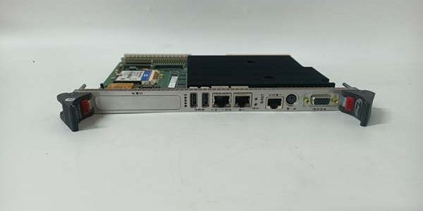
Product Core Brief
- Model: VMIVME-5565-110000
- Brand: GE
- Series: VMIC Fiber Reflective Memory VMEbus Node Card
- Core Function: Create hardware-synchronized shared memory rings for low-latency real-time data exchange across distributed VME racks
- Product Type: Single-width 6U VME64x reflective memory interface board
- Key Specs: 128 MB ECC SDRAM | 2.12 GBaud optical fiber | 256-node network capacity ⚠️ EOL — limited stock remaining
Product Introduction
GE mirrors local memory writes across all ring nodes via hardwired fiber transceivers, no OS driver overhead to add scan delay. It delivers consistent shared memory access for Mark V turbine control loops. This unit differs fromVMIVME-5565-064000 variant by doubling onboard memory and adding dual DMA engines. It holds inter-node latency under 500 ns and supports 4–64 byte dynamic packet sizing across 0 °C to +65 °C cabinet operating bands.
Key Technical Specifications
| Parameter | Value |
|---|---|
| Onboard reflective memory | 128 MB ECC-protected SDRAM |
| Fiber serial line speed | 2.12 GBaud duplex LC optical transceivers |
| Sustained data throughput | 170 MB/s (64-byte maximum packet frames) |
| Inter-node transfer latency | <500 ns point-to-point hardware copy |
| Network topology options | Unidirectional fiber ring or star via external hub |
| Supported node count per ring | Maximum 256 independent VME chassis nodes |
| Optical cable limits | 300 m multi-mode HCS; 10 km single-mode fiber |
| VMEbus compliance | VME64x, A16/A24/A32 address space, master/slave operation |
| DMA allocation | Dual independent DMA engines for read/write offload |
| Interrupt support | VME IRQ levels 1 through 7, network-wide event triggers |
| Auxiliary power rails | 5 V DC 3.5 A typical draw; 3.3 V DC 0.7 A typical draw |
| Operating cabinet temperature | 0 °C to +65 °C with minimum 300 LFM airflow |
| Storage temperature range | -40 °C to +85 °C |
| Mechanical form factor | Single-width 6U Eurocard VME slot |
| Net unit weight | 0.07 kg |
| Compliance standards | IEC 61000-6-2, CE Class A industrial certification |
Quality Control Process (Engineer’s Perspective)
- Incoming Verification: Cross-reference serial numbers against GE Mark V VME spare database to flag counterfeit hardware. Inspect LC fiber ports, VME gold edge pins and front status LEDs with a 10x magnifier for pin corrosion or cracked PCB traces; log serial numbers for gas turbine plant traceability.
- Live Functional Test: Seat the unit on a multi-node VME test rack paired with VMIVME-7807 SBCs and matched fiber trunk cables. Run continuous 26-hour load testing while logging cabinet temperature swings and measuring end-to-end memory copy latency under full 128 MB memory mapping.
- Electrical Parameter Test: Use a 500 V Megger to measure insulation resistance between fiber transceivers and chassis ground; pass threshold set at >10 MΩ. Verify PE protective ground loop resistance below 0.5 Ω with a Fluke 115 multimeter.
- Firmware Verification: Read and record onboard FPGA logic revision printed on PCB silkscreen. Photograph fiber ring termination jumper positions and VME IRQ select headers for field commissioning reference.
- Final QC & Packaging: Wipe unit front panel with anti-static microfiber cloth, cap both LC fiber ports with plastic dust covers. Seal inside a shielding ESD bag, attach a QC Passed label stamped with full test completion date.
Replacement Pitfall Guide
❗ Firmware Mismatch: FPGA v2.7 drops backward compatibility with older VMIVME-7807 SBCs running VxWorks v5.3. Match exact FPGA and OS runtime builds before rack power-up, or all ring memory writes fail to replicate across nodes indefinitely. ❗ DIP Switch / Jumper Misconfiguration: Factory default fiber ring termination bypass is disabled. Most multi-chassis turbine racks require the bypass jumper enabled on the last node in the fiber loop; missed settings create cyclic ring timeouts and missing trip setpoint data. ❗ Terminal / Cable Incompatibility: This unit uses LC duplex fiber connectors, unlike legacy ST-terminated VMIVME-5560 series cards. Unpolished fiber tips cause constant CRC packet retries under peak control load; cable bend radius must stay above 8× jacket diameter to preserve internal cladding layers. ❗ Power Supply Mismatch: Full memory DMA and fiber traffic draw 3.5 A on the 5 V rail. Calculate rack power budget with 20 % overhead; undersized VME backplane supplies trigger low-voltage lockout and broken ring synchronization. ❗ ESD Damage: Dry cabinet environments above 40 % relative static risk degrade internal fiber transceiver FPGA chips on the unit. Always use an anti-static mat and grounded wrist strap when handling exposed PCB edge connectors and LC fiber ports. Keep these in mind and you’ll cut 90% of rework time.
Compatibility Matrix & Benchmarks
Compatibility Matrix
- 4000 → : Needs Adaptation — memory capacity doubled, DMA engine count increased, identical VME pinout
- SBC → : Direct — full VMEbus memory mapping, minor ring node ID parameter adjustment required
- 5560 → : Incompatible — older ST fiber interface, different FPGA ring logic architecture





