
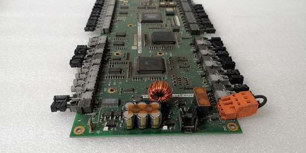
Product Core Brief
- Model: UFC760BE42 3BHE004573R0042
- Brand: ABB
- Series: UNITROL static excitation thyristor pulse & rotor feedback board for Advant OCS / Symphony Plus power control racks
- Core Function: Generates precise thyristor firing pulses for excitation power bridges and collects rotor field feedback signals to execute closed-loop generator voltage regulation
- Product Type: Horizontal rack-slotted pulse output & analog feedback interface PCB
- Key Specs: Multi-channel thyristor pulse outputs | Rotor current/voltage measuring inputs | Masterbus300 rack backplane communication
- Note: Full platform end-of-life; factory sealed new assemblies and fully cyclic load-tested surplus available for thermal, combined-cycle and hydro power plant excitation cabinet maintenance
Key Technical Specifications
- OEM article number: 3BHE004573R0042
- Pulse output capacity: 6-channel isolated thyristor gate firing pulse outputs for full-wave excitation bridges
- Rotor measuring inputs: 4–20mA / ±10V analog loops for field current, field voltage and temperature transducers
- Rack bus protocol: ABB proprietary Masterbus300 differential rack backplane bus
- Galvanic isolation rating: 1500 VAC between pulse power circuits and logic signal conditioning hardware
- Auxiliary operating supply: 24 VDC ±10% SELV, max 20 W continuous power draw
- Front diagnostic indicators: Green RUN power LED, BUS communication status light, red FAULT pulse/feedback fault alarm
- PCB surface treatment: ISA G3 conformal coating standard for coastal, offshore and chemical high-humidity cabinet environments
- Mechanical mounting: Standard horizontal UNITROL power rack clip-in slot design
- Operating ambient temperature: -10°C to +60°C sealed cabinet; storage -40°C to +85°C
- Humidity tolerance: ≤75% RH non-condensing below 55°C
- Enclosure rating: IP20 for interior cabinet installation
- Net assembly weight: 0.54 kg
- Overall dimensions: 178 mm H × 47 mm W × 233 mm D
- Compliance standards: IEC 60255 power protection standard, EU RoHS, CE certified
Product Introduction
This rack-mounted board delivers synchronized gate firing pulses to the thyristor power stage of static excitation systems, while simultaneously sampling rotor field feedback signals to close the voltage regulation control loop. Isolated pulse output circuits eliminate cross-channel noise interference during high-current excitation switching, and real-time BUS LED indicators let technicians verify valid Masterbus300 communication with the upper UFC760 series main control board without diagnostic software tools. All pulse timing logic relies on stable hardware oscillator circuits that maintain consistent firing angle resolution across full generator load ranges.
QA & Testing SOP (Transparency Building)
- Incoming Inspection: Cross-reference serial number against ABB UNITROL excitation spare asset database to filter counterfeit assemblies; inspect pulse terminal block array, rear backplane gold edge pins and front LED array with a 10x magnifier for thermal discoloration or pin corrosion; log serial numbers for full generator excitation system traceability records.
- Live Testing: Seat the unit on a standard UNITROL test rack paired with a UFC760BE143 main control board and thyristor power bridge load bank; supply rated 24VDC rack power; run a continuous 24-hour cycle test including firing angle full-range sweeps, rotor wire break fault injection and pulse channel short-circuit protection trigger validation.
- Electrical Testing: Use a Fluke 115 multimeter to verify full continuity across all 6 pulse output channels; measure ≥10MΩ isolation between pulse power terminals and rack chassis ground; confirm cabinet PE continuity resistance below 0.5Ω.
- Firmware/Config Backup: Record OEM firing pulse timing parameters and rotor transducer wiring polarity sequence printed on the PCB silkscreen for field commissioning reference.
- Final QC & Packaging: Wipe front panel surfaces with static-dissipative microfiber cloth; cap pulse terminal blocks and rear backplane edge connector with insulating dust covers; seal the assembly inside a shielding ESD bag, attach a printed QC tag with full 24-hour excitation pulse cycle test timestamp, then pack into foam lined transit cartons.
Installation Pitfalls & Guide (Engineer to Engineer)
❗ Mismatched main control board firmware generates firing angle offset: The board requires matching V277 revision UFC760 main controllers; mismatched firmware creates ±2% steady-state generator voltage swing violating grid code tolerances. ❗ Reversed rotor feedback wiring locks pulse output at minimum firing angle: Swapped field transducer wires trigger permanent under-excitation interlock until wiring correction and full rack power cycle completion. ❗ Over-torqued pulse terminal lugs fracture internal PCB traces: Sharp thermal cycling from cooling fans creates intermittent loss of thyristor firing pulses during peak generator load periods. ❗ ESD discharge destroys pulse timing oscillator ICs: Bare finger contact with PCB signal conditioning traces desynchronizes all six firing channels, requiring full excitation system shutdown and multi-day generator outage windows. ❗ Hot-swap energized 24VDC rack backplane corrupts Masterbus300 clock signals: Removing the unit under live power disables all pulse generation and rotor feedback sampling, opening an unprotected grid stability window for the power station.
4-step replacement guide
- Pre-install: Lock out and tag cabinet 24VDC auxiliary power supply breaker; wait 10 minutes for internal logic capacitors to fully discharge; don ESD wrist strap; capture photos of six-channel thyristor pulse wiring and rotor feedback transducer wiring layout.
- Removal: Disconnect all pulse output and rotor measuring terminal wires channel by channel following captured photos; release four front panel mounting fasteners, slide the old unit straight out of the rack slot without twisting rear edge connector pins.
- Install: Align the board with rack slot rails and seat fully inward until the latch clicks locked; re-terminate all pulse and rotor feedback wiring matching recorded polarity sequence to OEM specified torque values.
- Power-on Test: Restore 24VDC auxiliary power; confirm steady green RUN LED and active BUS communication indicator; inject calibrated rotor feedback signals to validate linear firing angle adjustment response; simulate broken rotor transducer wire to confirm red FAULT LED activates and logs excitation loop fault events to the plant SCADA server.
FAQ
Q: Can this unit operate without a paired UFC760 main control board inserted in the rack? A: It will generate fixed minimum-angle firing pulses, but all automatic voltage regulation and load compensation logic will be offline. A matched UFC760BE143 main control board is required to execute grid-compliant variable firing angle control sequences. Q: Is hot-swapping supported while cabinet 24VDC auxiliary power remains energized? A: It is not supported. The live differential Masterbus300 backplane carries high-speed control frame data; unplugging the board creates voltage transients that disrupt pulse timing and force the main excitation controller to cold restart, removing active generator voltage regulation. Full power lockout and 10-minute capacitor discharge wait time are mandatory before removal. Q: What warranty coverage applies to stocked units? A: Factory-new original thyristor pulse & feedback boards carry a 12-month OEM warranty covering six-channel pulse output drivers, rotor signal conditioning circuits, isolation transformers and front diagnostic LED arrays. Continuity-tested surplus units come with a 6-month functional warranty. Damage from reversed rotor transducer wiring, over-torqued pulse terminals or ungrounded ESD handling voids all warranty coverage. Q: What hardware replaces this unit for new power station UNITROL deployments? A: New UNITROL 6800 systems integrate pulse generation and rotor feedback sampling directly on the main UFC780 control board, eliminating separate rack-slotted pulse boards. This hardware is only approved for one-to-one maintenance replacement of pre-2022 legacy Advant OCS excitation racks. Q: Will stored firing angle calibration parameters be lost after full cabinet power outage? A: All pulse timing and gain characteristics rely on passive PCB resistor networks; no non-volatile memory stores tuning values on this hardware, so power loss does not alter operational behavior. Only physical terminal wiring polarity requires manual verification post-replacement. Q: What are the most common failure modes for a faulty unit? A: Persistent red FAULT LED with correct rotor transducer wiring, single-channel loss of thyristor firing pulses under load, fixed minimum firing angle output with valid Masterbus communication, degraded isolation causing cross-channel pulse interference, blank front RUN LED with normal 24VDC rack supply, and incomplete rotor field current/voltage feedback data logging to the excitation controller history.
Can you provide more details about the product’s features and applications?
What are the advantages of using this product compared to other similar products?
Are there any accessories or spare parts available for this product?





