
Product Core Brief
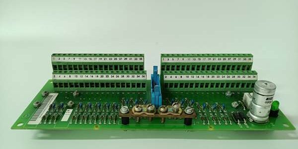
- Model: SCYC55830, Full OEM Part Code: 58063282A
- Brand: ABB Hitachi Energy
- Series: ABB Industrial Automation & Power Plant DCS / Drive auxiliary signal processing printed circuit board
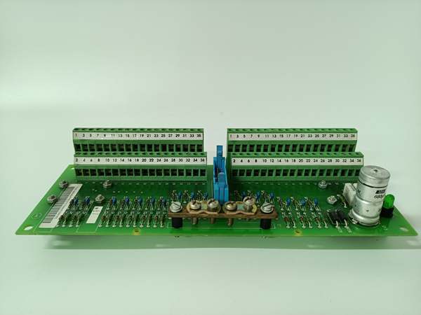
- Core Function: A multi-channel general-purpose I/O acquisition PCB designed to collect discrete digital status signals and analog process measurement signals from field sensors, limit switches, contactors and transmitters. It isolates field-side 24VDC signals from internal low-voltage logic circuits, filters industrial EMI noise, and transmits processed signal data to upper-level controllers (AC800M, 800xA DCS, RDCU/NDCU ACS800 drive control units). The board carries dense terminal blocks for massive field wiring connection and continuous signal monitoring for safety interlock, alarm and process control logic.
- Product Type: Multi-channel Digital & Analog I/O Signal Processing PCB
- Key Specs: 24VDC internal logic supply; mass multi-group terminal block layout for DI/DO/AI/AO; full functional galvanic isolation between field circuits and control logic; integrated RC EMI filter network; ISA G3 anti-corrosion conformal coating; wide operating temperature range; compatible with ABB 800xA DCS, AC800M PLC and ACS800 series wind/industrial converters
- Note: Standard industrial automation spare part still available in production; factory sealed new PCBs and fully bench-tested surplus boards are widely supplied for thermal power plants, offshore wind farms, chemical workshops and mining plant control cabinet maintenance. The whole PCB is coated with conformal coating to resist moisture, salt fog and corrosive gas for harsh industrial environments.
Key Technical Specifications
| Parameter | Value |
|---|---|
| Full OEM Article Number | , 58063282A |
| Operating Logic Supply | 24 VDC ±10% internal cabinet auxiliary power |
| Signal Channel Configuration | Large quantity of galvanically isolated digital input terminals, relay digital output terminals, analog voltage/current input/output terminals |
| Analog Signal Compatibility | 0–10 V voltage / 4–20 mA current analog signals, 12-bit sampling precision |
| Isolation Rating | Functional isolation ≥ 500 VAC between field signal circuits and internal logic PCB |
| EMI Suppression | Built-in RC absorption filter to eliminate high-frequency switching noise from MCC and IGBT drives |
| PCB Surface Treatment | ISA 71.04 G3 anti-salt, anti-moisture conformal coating |
| Cabinet Installation | Fixed bracket mounting inside DCS or converter control cabinet |
| Continuous Operating Ambient Temp | -20 °C ~ +55 °C inside sealed cabinet; storage: -40 °C ~ +70 °C |
| Humidity Limit | ≤75% RH non-condensing |
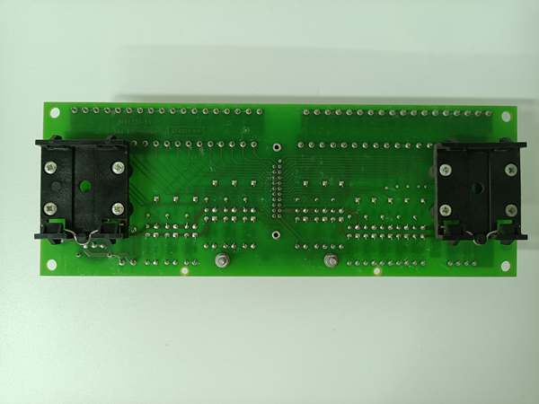
| Overall Board Dimensions | 260 mm L × 160 mm W × 22 mm D |
| Net Weight | Approx. 450 g |
| Compliance Standards | IEC 61800-3 EMC for variable speed drives, IEC 60255 industrial control equipment standard, CE & RoHS certified |
Product Introduction
The (58063282A) is a universal multi-channel I/O interface PCB widely used in ABB distributed control systems and ACS800 series large power converters. It serves as the intermediate signal bridge between field site equipment and main control hardware, undertaking three core signal processing tasks:
- Field Digital Signal Acquisition & OutputIt collects binary switch signals such as emergency stop, equipment running feedback, breaker position and interlock status via digital input terminals, and outputs relay control signals to auxiliary valves, local alarm lamps and contactors through digital output terminals. All DI/DO channels are equipped with independent galvanic isolation to avoid cross-circuit interference.
- Analog Process Signal Sampling & TransmissionMulti-channel analog input ports receive continuous process signals from pressure, flow, temperature and vibration transmitters, while analog output channels feed real-time motor speed, torque and grid voltage data to local display meters and secondary PLC systems for closed-loop regulation.
- EMI Filter & Continuous Signal Self-DiagnosisIntegrated RC filter circuits suppress high-frequency electromagnetic interference generated by drive IGBT switching and high-power equipment startup, preventing signal distortion and false protection trips. Continuous self-check circuit monitors wiring continuity and sensor loop integrity; once abnormal signal loss occurs, fault diagnostic codes will be uploaded to the DCS controller for maintenance alert.
With full conformal coating protection, the board can operate stably for long periods in high-humidity, corrosive industrial environments including offshore wind turbine cabinets and metallurgical workshops. It is a standard auxiliary signal matching board for ABB 800xA DCS, AC800M PLC and ACS800 wind farm converters, and cannot work independently without matched upper-layer control hardware.
QA & Testing SOP (Transparency Building)
- Incoming Visual Inspection: Cross-check full part number 58063282A and serial number against ABB industrial spare parts database to reject counterfeit mismatched PCBs; inspect terminal screw blocks, PCB traces, sampling circuits and conformal coating for burn marks, discoloration, salt corrosion or pin bending damage; record serial numbers and production batches for full traceability.
- Full Bench Linkage Test: Install the board on standard DCS/drive test rack, supply stabilized 24VDC logic power, connect simulated digital switches and analog signal generators; run 24-hour cyclic testing including DI/DO signal transmission accuracy, analog signal sampling calibration, EMI noise filter simulation and communication linkage with AC800M/RDCU control units, verify no false operation under grid fluctuation simulation.
- Electrical Insulation Test: Use insulation resistance tester to confirm isolation resistance ≥ 10 MΩ between field signal terminals and internal logic circuits; test chassis ground continuity resistance below 0.5 Ω.
- Hardware Record Backup: Record PCB hardware version, photograph all terminal pin definitions and wiring sequence for field commissioning reference.
- Final QC Packaging: Wipe PCB surface with anti-static microfiber cloth, cover all terminal blocks with insulating dust caps, place the board into independent ESD shielding bag, attach unified printed QC test tag with technician ID and full 24-hour cyclic test runtime timestamp, then pack into foam shockproof carton for long-distance power plant transportation.
Installation Pitfalls & 4-Step Replacement Guide
Common Installation Hazards
❗ Residual High Voltage Risk: Before disassembling the board, fully lock out cabinet 24VDC auxiliary power and wait for internal capacitor discharge to avoid electric shock caused by residual charge on signal loops.❗ ESD PCB Damage Risk: Must wear certified anti-static wrist strap during all disassembly and installation work; bare hand contact with internal sampling chips and filter circuits will permanently damage signal processing performance.❗ Terminal Wiring Polarity Reversal: Reverse positive/negative wiring of 24VDC digital or analog signals will burn the board’s internal signal acquisition circuit instantly.❗ Loose Terminal Torque Defect: Under-tightened wire terminals create high contact resistance, leading to overheating during long-term operation and unstable signal reading drift.❗ Connector Pulling Damage: Hold plastic terminal housing instead of wires when plugging/unplugging connectors to prevent internal pin breakage and open-circuit faults.
4-Step Board Replacement Guide
- Pre-install Preparation: Lock out and tag out the cabinet 24VDC auxiliary power supply feeding the board, wait for complete capacitor discharge, wear ESD wrist strap, photograph all digital/analog terminal wiring sequences and fixed mounting bolt positions inside the control cabinet.
- Removal Operation: Loosen all terminal wire screws one by one following photographed records, unscrew the board bracket fixing bolts, take out the old PCB from the cabinet mounting frame.
- Installation & Wiring: Fix the new board onto the original bracket with standard torque bolts; re-terminate all digital and analog field wires strictly following photographed wiring sequence, ensure every terminal screw is tightened to ABB specified torque without loose strands.
- Power-on Commissioning Test: Restore cabinet 24VDC auxiliary control power, run static signal calibration without main high-power input; simulate digital switch and analog sensor signals to verify accurate signal collection and output function, upload DCS diagnostic logs to confirm no persistent I/O fault alarms during continuous no-load operation.
FAQ
Q: What is the core difference between and drive main circuit boards such as RINT-5611C?A: is a low-voltage field digital/analog signal acquisition board, responsible for collecting external sensor and switch signals without high-power IGBT drive or current sampling functions. RINT-5611C is a power stage interface board installed on the IGBT power stack side, executing IGBT pulse drive, three-phase current sampling and power module temperature detection. The two boards belong to different signal layers and cannot replace each other.
Q: Can be hot-swapped while the cabinet auxiliary power is energized?Strictly prohibited. The board connects to live 24VDC signal loops and internal logic power circuits; disassembly under energized conditions will cause signal surge and permanent damage to PCB sampling chips. Full auxiliary power lockout is mandatory before replacement.
Q: What warranty applies to stocked 58063282A boards?Factory-new original PCBs carry 12-month official ABB manufacturer warranty covering all digital/analog signal channels, EMI filter circuits and PCB substrate. Bench-tested surplus boards provide 6-month functional warranty; damage caused by power polarity reversal, residual high voltage shock or ungrounded ESD handling voids all warranty terms.
Q: Has ABB discontinued production?No formal EOL notice issued; remains standard supply for new ABB 800xA DCS and ACS800 drive cabinet renovation projects. It is the general-purpose multi-channel I/O signal board for conventional industrial and power plant automation systems.
Q: What typical faults indicate a defective board?Common failure symptoms: Random digital input signal loss without field switch fault, analog measurement value drift or constant abnormal reading, failure to output relay control signals to field actuators, frequent EMI interference causing DCS communication fluctuation, and persistent I/O loop fault alarms with intact external wiring.




