
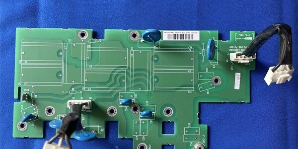
Product Core Brief
- Model: RVAR-5612, official OEM spare part code: 64714996
- Brand: ABB Hitachi Energy
- Series: ACS800 series industrial & wind turbine variable frequency converter main circuit protection PCB
- Core Function: Dedicated three-phase varistor surge suppression and line filtering board installed on the AC input side of ACS800 power units. It integrates high-energy metal oxide varistors (MOVs) and RC absorption circuits to absorb transient grid surge voltage, lightning impulse spikes and switching voltage spikes generated by contactors or nearby power equipment. It suppresses overvoltage transients to protect the rectifier bridge, DC bus capacitors and IGBT power modules from surge breakdown, while also filtering high-frequency grid EMI noise to improve drive operation stability.
- Product Type: Main Circuit Varistor Surge Protection Printed Circuit Board
- Key Specs: Three-phase symmetrical varistor absorption circuit; built-in RC snubber filter network; matched with medium/high power frame sizes of ACS800 converters; conformal anti-corrosion PCB coating; no external auxiliary power required, directly connected to three-phase AC input terminals
- Note: ABB fully discontinued the drive platform including ; limited factory-sealed original PCBs and fully bench-tested surplus boards are supplied for legacy wind farm, metallurgy, water treatment and mining drive cabinet emergency maintenance.
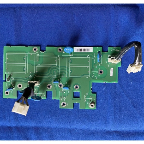
Key Technical Specifications
| Parameter | Value |
|---|---|
| Full OEM Part Number | , 64714996 |
| Application Range | Medium & high power converter power drawers |
| Surge Protection Structure | 3-phase independent MOV varistor per phase + RC absorption loop |
| Rated Grid Voltage Compatibility | 380V / 400V / 480V three-phase AC industrial grids |
| Maximum Surge Energy Absorption | Matched to power unit rated surge withstand capacity |
| EMI Filter Function | RC snubber suppresses high-frequency switching noise between L1/L2/L3 phases |
| PCB Anti-Corrosion Treatment | ISA 71.04 G3 conformal coating for offshore, high-humidity, corrosive environments |
| Installation Position | Inside power unit drawer, pre-wired on AC input busbar terminals |
| Enclosure Rating | IP20 board-level protection, sealed inside converter cabinet |
| Operating Ambient Temperature | -20 °C to +50 °C continuous cabinet operation; storage range -40 °C ~ +70 °C |
| Mechanical Dimensions | 300 mm W × 155 mm L × 10 mm D |
| Net Weight | Approx. 330 g |
| Compliance Standards | IEC 61800-3 EMC for variable speed drives, IEC 61643 surge protection standard, CE & RoHS certified |
Product Introduction
The is a critical passive surge protection component for ABB series medium and high-power converters, widely deployed in wind turbine full-power converters, large industrial motor drives for fans, pumps, crushers and rolling mills.It executes two core protection tasks for the converter main circuit:
- Transient Overvoltage Surge Suppression: Three independent metal oxide varistors connected across each phase-to-phase AC input line absorb high-voltage transient surges caused by lightning strikes, grid switching operations, nearby large motor startup or contactor breaking spikes. The varistors instantly clamp abnormal surge voltage to a safe level, preventing breakdown of rectifier diodes, DC bus electrolytic capacitors and IGBT power modules.
- High-Frequency EMI Noise Filtering: Integrated RC snubber circuits between each phase line absorb high-frequency interference generated by grid switching devices, reducing conducted electromagnetic noise that would otherwise cause unstable drive communication, false protection trips or signal distortion on analog/digital I/O boards like RMIO-11C and RINT-5611C.
The PCB adopts full conformal coating treatment to resist salt fog, moisture and industrial corrosive gas, making it reliable for offshore wind turbine converter cabinets and metallurgical workshop environments. It operates passively without requiring external 24V auxiliary power, directly tapping onto the three-phase AC input busbar of the power drawer for seamless integration. Without a functional , the converter main power stage faces severe risk of permanent damage during grid transient events.
QA & Testing SOP (Transparency Building)
- Incoming Visual Inspection: Cross-check full part number 64714996 and serial number against ABB spare parts database to reject counterfeit mismatched boards; inspect varistor components, RC snubber resistors/capacitors, busbar terminal lugs and conformal coating for burn marks, cracking, corrosion or discoloration; record serial numbers and production batches for full traceability.
- Surge Bench Test: Mount the board onto standard power unit test rack, connect three-phase simulated AC grid input; apply standard lightning impulse surge voltage per IEC 61643 to verify phase-to-phase surge clamping performance, check RC filter noise suppression effect and confirm no component overheating during continuous surge cycling for 24 hours.
- Electrical Insulation Test: Use insulation resistance tester to confirm isolation resistance ≥ 10 MΩ between each phase circuit and PCB ground substrate; test chassis ground continuity resistance below 0.5 Ω.
- Hardware Record Backup: Record PCB hardware revision, photograph busbar terminal connection sequence and mounting bracket positioning dimensions for field reference.
- Final QC Packaging: Wipe PCB surface with anti-static microfiber cloth, cover all metal busbar terminals with insulating protective caps, place the board into independent ESD shielding bag, attach unified printed QC test tag with technician ID and full 24-hour surge test runtime timestamp, then pack into foam shockproof carton for long-distance transportation.
Installation Pitfalls & 4-Step Replacement Guide
Common Installation Hazards
❗ Lethal DC Bus Residual High Voltage Risk: After shutting down the drive main AC input power, wait a minimum of 15 minutes for full discharge of DC bus capacitors before disassembling the power drawer and board to avoid electric shock.❗ Incorrect Phase Sequence Wiring: Misaligned L1/L2/L3 busbar connection will unbalance three-phase surge suppression performance, leading to uneven overvoltage protection and early varistor aging; photograph original busbar wiring before removal for reference.❗ ESD PCB Damage Risk: Must wear certified anti-static wrist strap during all disassembly and installation operations; bare hand contact with PCB varistor and snubber components will degrade surge absorption performance.❗ Loose Busbar Terminal Torque: Under-tightened busbar lugs create high contact resistance, causing local overheating during high current operation and burning varistor components; follow ABB specified torque values for terminal fastening.❗ Missing Insulation Barriers: After replacement, reinstall original plastic insulation barriers between and adjacent high-power metal busbars to prevent phase short-circuit hazards.
4-Step Board Replacement Guide
- Pre-install Preparation: Perform full lockout/tagout on the converter main three-phase AC input power, wait 15+ minutes for DC bus capacitor complete discharge, wear ESD wrist strap, photograph L1/L2/L3 AC busbar connection positions and mounting bracket fixing bolts of the board inside the power drawer.
- Removal Operation: Loosen the busbar terminal nuts connected to the PCB, unscrew the bracket fixing bolts, separate the old board from the power drawer internal busbar assembly.
- Installation & Wiring: Fix the new board onto the original mounting bracket with standard torque bolts; re-connect L1/L2/L3 three-phase busbars strictly following the photographed wiring sequence, ensure all terminal nuts are fully tightened without loose contact, re-fit plastic insulation barriers.
- Power-on Commissioning Test: Restore converter main AC input power, run drive no-load operation for 1 hour, monitor converter fault history for surge overvoltage alarms; simulate minor grid voltage fluctuations to verify stable operation without random overvoltage trips triggered by transient spikes.
FAQ
Q: What is the difference between and RINT-5611C?A: is a passive AC input surge protection & EMI filter board without signal sampling or IGBT drive functions, installed on the grid side of the power unit. RINT-5611C is the main circuit interface board responsible for IGBT pulse drive, three-phase current sampling and power module temperature detection, located between the control unit and IGBT power stack. The two boards work collaboratively and cannot replace each other.
Q: Can be hot-swapped with the converter energized?A: Strictly forbidden. The board is directly connected to live three-phase high-voltage AC busbars; disassembly under energized conditions will cause severe arc flash accidents and fatal electric shock. Full main power lockout and DC bus capacitor discharge are mandatory before replacement.
Q: What warranty applies to stocked boards?A: Factory-new original PCBs carry 12-month official ABB manufacturer warranty covering varistor surge absorption circuits, RC filter networks and PCB substrate. Bench-tested surplus boards provide 6-month functional warranty; damage caused by residual high voltage shock, loose busbar contact overheating or ungrounded ESD handling voids all warranty terms.
Q: Has ABB discontinued production?A: Yes, the entire converter platform including surge protection board is fully end-of-production. New industrial and renewable energy projects adopt updated ACS880 series converters with integrated surge protection hardware built into the power unit frame; is only supplied as spare parts for legacy drive fleets.
Q: Will drive motor control parameters be affected after replacing ?A: All motor control curves, overload thresholds and protection logic settings are stored in the RMIO/RDCU control unit flash memory, which is completely independent of the surge board. No parameter backup or recalibration is required after replacement, only a short no-load test to verify surge protection stability.
Q: What typical faults indicate a failed board?A: Common failure symptoms: Frequent random overvoltage transient fault trips during grid voltage fluctuations, varistor component burning with blackened PCB traces, excessive EMI noise causing unstable DDCS fiber communication between control unit and power stack, abnormal interference drift on analog sensor signal readings, and premature breakdown of DC bus capacitors without other grid faults.




