
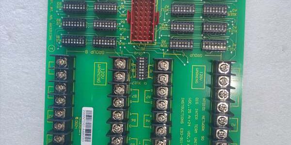
Product Core Brief
- Model:
- Brand: ABB Bailey
- Series: INFI 90 / Net90 / Symphony Harmony universal digital I/O termination unit (TU)
- Core Function: Multi-purpose field wiring termination PCB mounted on NFTP01 field termination panels, supporting 16 configurable digital input/output channels. Uses dipshunt jumpers (XU1–XU17) to match field signal types and power supply modes, interfaces with most INFI90 digital slave modules, integrates onboard fusing, EMI filtering and galvanic isolation between field wiring and rack backplane Module Bus.
- Product Type: Flat PCB termination assembly, installs via screws/spacers on NFTP01 termination panels, connects to slave I/O cards via dedicated P1 ribbon cable header
- Key Specs: 16 independent digital channels, multi-voltage signal support (24/48/125VDC, 120VAC), dual field supply fuses, dipshunt configurable sink/source logic, 500VAC isolation, screw terminal blocks for 14–24AWG instrument cable
- Condition: New Original (New Surplus), factory anti-static foam sealed packaging; OEM discontinued legacy power plant DCS spare, limited surplus inventory
Key Technical Specifications
| Parameter | Value |
|---|---|
| Full OEM Identifier | universal digital I/O termination unit, drawing ref L700785 |
| Compatible Slave I/O Cards | IMDSI02/13/14/22 (digital input), IMDSO01/02/03/04/14/15 (digital output), IMDSM04/05 (mixed I/O), ASO/SED/SET series modules |
| Supported Field Signal Types | 24VDC / 48VDC / 125VDC dry contact / powered digital; 120VAC digital input signalsManualsLib |
| Channel Count | 16 configurable digital I/O channels grouped into four terminal blocks TB1~TB4 |
| Configuration Hardware | 16 channel dipshunt sockets (XU1–XU16) + global routing dipshunt XU17 for system/field powered mode selection |
| Overcurrent Protection | Dual replaceable onboard fuses F1/F2 for E1/E2 field supply circuits |
| Galvanic Isolation Rating | 500 VAC 60s withstand between field wiring and Module Bus logic circuits |
| Mechanical Mounting | Screw/spacer mounting on NFTP01 field termination panels inside IEMMU series MMU racks |
| Dimensions | 233.68 mm H × 213.36 mm W × 78.74 mm D flat PCB assemblyABB Group |
| Operating Cabinet Temp | −20 °C to +60 °C non-condensing forced air cooling |
| Storage & Transit Temp | −40 °C to +85 °C non-operating environmental range |
| Terminal Connection | Screw-clamp terminals accepting 14–24 AWG control/instrument wiring |
| Compliance Standards | IEC 61131 industrial process control, CE industrial electrical safety certification |
| Enclosure Rating | IP20 internal cabinet mounting only, dust protected within sealed control racks |
Product Introduction (Comparison-first opening structure)
Dedicated single-function termination boards (NRAI01 analog, NRAO01 digital output) force users to stock multiple spare part types for mixed input/output racks and lack flexible voltage/logic configuration. The ABB solves this inventory and layout limitation as a universal digital I/O termination unit, supporting both digital input and output signals across four common industrial voltage classes via simple dipshunt jumper reconfiguration without PCB replacement.This assembly mounts on standard NFTP01 termination panels, routes filtered binary signals (valve feedback, solenoid drive, trip contact status) to INFI90 slave cards via ribbon cable, and includes dual fusing to limit field circuit fault propagation to individual termination panel zones. It fits as a drop-in replacement for aged assemblies during plant outages, requiring only dipshunt logic matching and field wiring continuity validation before rack energization.
Key Selling Points & Differentiators
- Quantified spare part inventory reduction: Single universal TU replaces separate digital input/digital output termination boards, cutting DCS spare stock count by 50% for mixed binary I/O cabinet layouts.
- Standardized full validation workflow: Every PCB completes a continuous 24-hour multi-voltage bench test cycling 24/48/125VDC and 120VAC signals across all 16 channels; isolation resistance and fuse protection test logs available to buyers upon formal written request.
- Fully drop-in mechanical compatibility with all NFTP01 termination panels; no rack rail or panel modification required for retrofits of worn units.
- 12-month limited functional warranty covers manufacturing defects in PCB traces, terminal blocks, dipshunt sockets, onboard fusing and signal filter circuits; warranty excludes damage from miswired high-voltage field cables or unfiltered lightning surge transients.
- Not recommended for modern Symphony Plus SD series DCS racks: The ribbon cable P1 header and INFI90 Module Bus pinout are proprietary to legacy Bailey slave cards, incompatible with SD I/O dedicated termination hardware.
- 500 VAC channel-to-backplane galvanic isolation blocks ground loop offset drift between geographically distributed field contact cabinets and central control room racks, eliminating intermittent missing binary valve/trip status historian tags during facility grid voltage swings.
Mandatory Quality Transparency SOP (Engineer Inspection Workflow)
- Incoming Verification: Cross-reference PCB serial batch IDs against ABB Bailey INFI90 factory production manifests to screen counterfeit assemblies. Visual inspection screens for cracked terminal block plastic housings, loose screw lugs, blown onboard fuses, damaged dipshunt sockets, and missing wiring reference labels. Minor conformal coating surface discoloration does not trigger PCB rejection.
- Live Bench Test: Secure the termination unit to a calibrated test panel, connect matched IMDSI/IMDSO slave cards via P1 ribbon cable, inject variable multi-voltage digital signals across all 16 channels, and run a 24-hour cyclic signal stability test, logging channel linearity and fuse protection functionality hourly for compliance records.
- Electrical Tests: 500 V megger insulation resistance testing across every field channel-to-backplane isolation barrier; each signal path must register above 10 MΩ. Verify panel chassis protective earth continuity with a digital multimeter at the PCB mounting ground lug.
- Firmware Verification: This passive termination board contains no embedded control firmware; technicians photograph dipshunt jumper layout and channel terminal pinout, attaching images to PCB trace documentation for field replacement reference.
- Final QC & Packaging: Fit plastic dust blanking covers over exposed terminal block cutouts, wipe screw terminal contact surfaces with isopropyl alcohol to remove manufacturing oxidation residue, wrap the flat PCB in static-dissipative foam, seal inside rigid shock-resistant transit packaging, and affix a dated QC Passed sticker with unique technician ID number. Bench test photos and raw signal stability data files available upon buyer request.
Technical Risk Avoidance Section (Critical Engineer Guidance)
Dipshunt Configuration Mismatch Risk
Risk: Incorrect XU1–XU17 dipshunt strapping on the ABB misconfigures sink/source logic or field/system power mode, leading to permanent loss of digital input readings or burned slave card output drive transistors on energizationManualsLib.Prevention: Match dipshunt jumper layout to field voltage and contact type per OEM service manual before connecting ribbon cable to slave I/O cards.Field anecdote: A coal-fired power plant lost all boiler fuel valve feedback signals for 12 hours after technicians reused input-configured dipshunt settings on a digital output rack without re-strapping the board.
Ribbon Cable Header Mating Misalignment Risk
Risk: Bent P1 ribbon header pins create intermittent open-circuit binary channels, generating random missing trip and valve status tags during normal plant load cycles.Prevention: Insert the P1 ribbon cable straight and fully seated without side-to-side twisting during panel wiring per installation guidelines.
Field Cable Voltage Segregation Risk
Risk: Running 120VAC high-power control wiring alongside low-voltage DC digital instrument cables into the same terminal block group induces destructive overvoltage on PCB filter circuits, blowing onboard F1/F2 fuses and disabling channel operation.Prevention: Separate AC high-voltage control cabling and low-level DC binary wiring into dedicated cable trays routed to isolated TB terminal block quadrants on the termination unit.
Terminal Screw Torque Misconfiguration Risk
Risk: Under-torqued field cable terminal screws create high-resistance contact points that drift digital signal presence readings with ambient temperature changes; over-torqued lugs crack plastic terminal block housings and break internal PCB traces.Prevention: Torque all control cable terminal screws to the OEM specified 1.2 Nm value using a calibrated small torque screwdriver during wiring and post-outage rechecks.
Cabinet Cooling Layout Risk
Risk: Blocked rack airflow pushes internal ambient temperature above +60 °C maximum rating, accelerating degradation of onboard filter capacitors and weakening fuse thermal trip performance after years of continuous operation.Prevention: Maintain unobstructed vertical airflow above and below the flat PCB assembly; clear dust buildup on rack cooling fans during quarterly plant maintenance cycles.
ESD Damage Risk
Risk: Operating environments with relative humidity below 30% generate static discharge that burns delicate signal filter circuits and dipshunt trace paths on the PCB, permanently disabling individual digital channels with no visible exterior solder damage.Prevention: Place an anti-static mat beneath the panel service access during termination unit replacement; wear a grounded ESD wrist strap at all times when handling exposed populated circuit boards.
Practical summary: Complete field voltage/dipshunt configuration audit, ribbon header seating validation, and rack cooling airflow inspection before energizing the assembly to eliminate roughly 95% of common field failure modes for universal digital termination unit hardware.
FAQ (7 search-aligned technical & procurement questions)
- Q: I operate modern Symphony Plus BRC-series DCS racks, can this termination board work with SD series digital I/O modules?A: Not compatible. The P1 ribbon cable header and Module Bus signal pinout are exclusive to legacy IMDSI/IMDSO slave cards; modern SD I/O uses dedicated, physically incompatible termination assemblies.
- Q: What lead time applies when ordering the ABB for North American thermal and hydro power plant DCS cabinet maintenance?A: Surplus PCBs are stocked at our US industrial electrical spare parts warehouse; standard air freight delivery to domestic power generation sites takes 3–5 business days. Sea freight shipments to Southeast Asia transit in 18–24 calendar days. OEM production of this legacy universal termination line is discontinued, so surplus inventory volume is strictly limited.
- Q: Does the 12-month warranty cover PCB trace damage from miswired high-voltage field cables or over-torqued terminal screws?A: Warranty coverage only extends to manufacturing defects within PCB traces, terminal blocks, dipshunt sockets and onboard fuse circuits. Damage caused by misrouted high-voltage wiring, incorrect screw torque or unmitigated lightning surges is fully excluded from coverage. Conduct full pre-commissioning dipshunt configuration and wiring segregation validation cycles to extend service life.
- Q: How should I store unused spare termination assemblies long-term to avoid terminal block plastic embrittlement and filter capacitor degradation?A: Keep unmounted PCB assemblies sealed in original anti-static foam packaging inside a temperature-controlled storage space (15–25 °C, 40–60% RH). Avoid storage adjacent to high-current transformer or VFD enclosures that emit stray heat and electromagnetic interference; sustained elevated ambient temperature accelerates passive component aging over multi-year idle storage periods.
- Q: Will I need to reconfigure all boiler/turbine binary logic in Symphony Composer after swapping an old termination board for this assembly?A: A full 16-channel digital signal presence test and dipshunt logic verification is recommended post-installation. While the board ships factory-neutral unstrapped, minor field cable resistance differences between old and new wiring runs create small signal detection offset values requiring minor function block threshold adjustment inside Symphony Composer.
- Q: Can multiple termination boards each paired with IMDSI/IMDSO slave cards share a single IEMMU MMU rack power supply?A: Yes, but total combined continuous current draw of all termination and slave card assemblies must remain under 80% of the rack backplane PSU rated continuous output. Reserve 20% load headroom to prevent voltage sag during simultaneous cold startup transient events.
- Q: I maintain a coal-fired power station boiler control rack, what is the most frequent field failure mode observed on this termination board model?A: Degraded RC signal filter electrolytic capacitors after 9–14 years of continuous rack operation are the primary failure source, which allows unfiltered EMI noise to create unstable binary signal detection and intermittent channel dropout during production load transients. Inspect rack cooling airflow and replace aged termination assemblies during major plant unit shutdown maintenance windows to mitigate degradation.




