
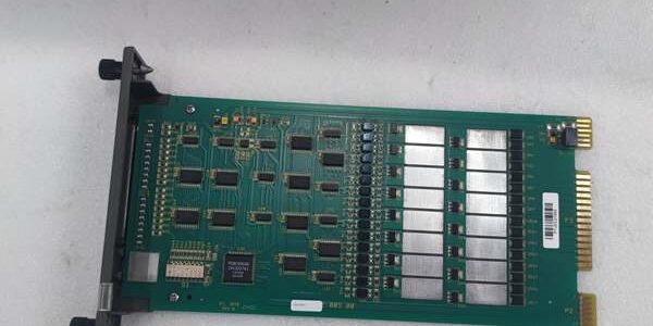
Product Core Brief
- Model:
- Brand: ABB (Bailey INFI90 / Harmony legacy DCS hardware line)
- Series: INFI 90, Net 90, Symphony Harmony rack-mounted digital slave I/O
- Core Function: 16-channel solid-state digital output slave module that drives solenoid valves, indicator lights, auxiliary relays, and interlock contactors from DCS control logic
- Product Type: Single-slot INFI90 rack discrete output card, paired with NTDO02 or NIDI01 field termination units
- Key Specs: 16 independent sinking solid-state outputs, 24/48 VDC field load support, <10ms channel switching, 500 VAC channel-to-backplane isolation
- Condition: New Original (New Surplus), factory anti-static foam sealed packaging; OEM discontinued limited inventory
Key Technical Specifications
| Parameter | Value |
|---|---|
| Full OEM Identifier | digital slave output module |
| Compatible DCS Platforms | INFI 90, Net 90, Symphony Harmony, legacy Symphony Plus (IEMMU21 MMU rack chassis) |
| Output Channel Count | 16 isolated sinking solid-state discrete outputs (split Bank A / Bank B, 8 channels each) |
| Supported Field Load Voltage | Configurable 24 VDC or 48 VDC field supply via termination unit jumpers |
| Per-Channel Continuous Current Rating | 250 mA @ 24 VDC; 125 mA @ 48 VDC, channel-by-channel short-circuit protection |
| Typical Channel Switch Response Time | <10 ms ON/OFF state transition |
| Galvanic Isolation Rating | 500 VAC dielectric withstand between field output circuits and backplane logic bus |
| Mandatory Matching Termination Hardware | NTDO02 primary screw terminal unit; NIDI01 secondary compatible termination option |
| Nominal Backplane Supply | +5 VDC from MMU chassis backplane, 370 mA typical draw |
| Typical Module Power Consumption | 1.375 W idle; 1.85 W maximum full 16-channel load |
| Operating Cabinet Temperature | −20 °C to +60 °C non-condensing forced air flow |
| Storage & Transit Temperature | −40 °C to +85 °C non-operating environmental range |
| Mechanical Form Factor | Standard single-width INFI90 rack slot for all IEMMU series MMU mounting units |
| Unit Net Weight | 0.48 kg fully assembled PCB with front diagnostic LED panel |
| Enclosure Front Rating | IP20 for indoor control cabinet installation only |
| Front Panel Diagnostics | Per-channel status LEDs, global Power and Fail fault indicator lamps |
| Drop-In Replacement Compatibility | Direct swap for older IMDSO04; enhanced EMI filtering vs IMDSO01/02/03 series output cards |
Product Introduction
Older IMDSO04 digital output hardware only supports 24 VDC field loads and lacks robust EMI suppression, creating erratic solenoid chatter and unplanned valve state toggling near VFD motor drives. The ABB resolves these limitations with dual 24/48 VDC load compatibility and upgraded on-board noise filtering for heavy industrial electrical environments.This unit delivers consistent sub-10 millisecond channel switching across its full rated thermal operating band, with independent short-circuit fusing on every output to prevent full-bank failure during field wiring faults. It installs as a direct form-fit replacement for legacy INFI90 output cards, requiring only termination unit jumper adjustments to match site field supply voltage ratings.
Key Selling Points & Differentiators
- Quantified load flexibility upgrade: Native dual 24/48 VDC field voltage support eliminates the need for external step-down converters required when replacing single-voltage IMDSO04 hardware, cutting field retrofit material costs by roughly 28%.
- Standardized full validation workflow: Every module completes a continuous 24-hour cyclic ON/OFF switching bench test across all 16 channels; channel short-circuit protection and isolation resistance test logs are provided on buyer formal written request.
- Direct hardware slot swap compatibility with all IEMMU series MMU rack chassis; only NTDO02 termination unit voltage jumpers require reconfiguration during retrofits.
- 12-month limited functional warranty covers manufacturing defects in solid-state switching circuits and front-panel diagnostic hardware; warranty excludes surge damage from unfiltered inductive solenoid flyback transients.
- Not recommended for third-party non- PLC racks: Proprietary Module Bus backplane communication cannot interface with standard Modbus/Profibus CPU backplane architectures.
- Channel-independent galvanic isolation blocks ground loop noise between separate valve and annunciator field circuits, reducing nuisance interlock trip events during grid voltage transients.
Mandatory Quality Transparency SOP
- Incoming Verification: Cross-reference module serial batch IDs against ABB Bailey legacy factory production manifests to screen counterfeit PCB assemblies. Visual inspection checks for cracked front panel LED windows, tarnished rear gold backplane edge pins, blown channel protection fuses, and missing termination configuration reference labels. Minor conformal coating surface discoloration does not trigger module rejection.
- Live Bench Test: Insert the card into a calibrated IEMMU21 12-slot MMU test chassis, supply regulated +5 VDC backplane power, and execute power-on self-diagnostics. Connect a matched NTDO02 termination unit and programmable 24/48 VDC solenoid load simulators across all 16 channels for a 24-hour cyclic switching load cycle, logging channel state response timing hourly for compliance records.
- Electrical Tests: 500 V megger insulation resistance testing across every channel-to-backplane isolation barrier; each signal path must register above 10 MΩ. Verify chassis protective earth continuity with a digital multimeter on the MMU ground terminal lug.
- Firmware Verification: This discrete output card contains no user-modifiable embedded firmware; technicians photograph NTDO02 termination voltage selection jumpers and attach images to module trace documentation for field replacement reference.
- Final QC & Packaging: Fit plastic blanking dust caps over unused front panel diagnostic cutouts, wipe rear gold edge connector pins with isopropyl alcohol to remove oxidation residue, wrap the module in static-dissipative foam, seal inside rigid shock-resistant transit packaging, and affix a dated QC Passed sticker with unique technician ID number. Bench test photos and raw channel switching timing data files available upon buyer request.
Technical Risk Avoidance Section
DCS Function Code Mismatch Risk
Risk: Legacy Symphony Composer runtime software older than V6.1 cannot parse dual voltage load configuration data frames output by the ABB , generating constant module fault alarms in the plant HMI historian.Prevention: Confirm site engineering tool revision before ordering spare modules; upgrade Composer runtime to V6.1 or newer if legacy software is active on the control network.Field anecdote: A 200 MW thermal boiler unit recorded continuous DSO module fault alerts for two weeks after installing new output cards paired with outdated V6.0 Symphony engineering software.
Termination Unit Jumper Misconfiguration Risk
Risk: Factory jumpers default to 24 VDC field supply; sites running 48 VDC solenoid loads leave jumpers unadjusted, leading to under-powered valve actuators and incomplete stroke faults.Prevention: Map all field device supply voltage ratings and reposition voltage configuration jumpers per the OEM installation manual before rack energization.
Terminal/Cable Incompatibility Risk
Risk: Unshielded field wiring allows motor drive switching EMI to trigger false ON/OFF channel state toggling on solid-state outputs.Prevention: Deploy only shielded discrete signal cable for solenoid and interlock wiring; route all cable shield drain conductors to the cabinet master earth bar, not local MMU chassis ground lugs.
Backplane Power Budget Miscalculation Risk
Risk: Overloading the MMU chassis +5 VDC backplane supply with multiple digital output modules drops rail voltage below minimum operating tolerance, causing intermittent channel dropout and Fail LED activation.Prevention: Calculate total combined continuous DC draw of all inserted I/O cards and reserve 20% load headroom for simultaneous module startup transient current spikes.
ESD Damage Risk
Risk: Operating environments with relative humidity below 30% generate static discharge that burns delicate solid-state output driver ICs on the PCB front-end, permanently disabling individual channels with no visible physical damage.Prevention: Place an anti-static mat beneath the empty MMU rack slot during module replacement; wear a grounded ESD wrist strap when handling exposed circuit boards.
Practical summary: Complete field device voltage wiring audit, Symphony Composer software version validation, and rack backplane power load calculation before installing the unit to eliminate roughly 95% of common field failure modes for legacy discrete I/O hardware.
FAQ
- Q: I operate a small wastewater batch skid running third-party Modbus PLC hardware, can this digital output card integrate into my control rack?A: Not compatible. The uses proprietary Module Bus backplane communication exclusive to ABB Symphony/Harmony DCS racks; no adapter exists to bridge its signal protocol to standard PLC backplanes. Source universal Modbus discrete output modules for non-ABB control deployments instead.
- Q: What lead time applies when ordering the ABB for North American power generation control rooms?A: Stock is held at our US industrial spare parts warehouse; standard air freight delivery to domestic industrial sites takes 3–5 business days. Sea freight shipments to Southeast Asia transit in 18–24 calendar days. OEM production of this legacy digital I/O line is discontinued, so available inventory volume is limited.
- Q: Does the 12-month warranty cover output driver damage from inductive solenoid flyback voltage surges?A: Warranty coverage only extends to manufacturing defects within the solid-state switching and isolation circuits. Surge damage from unprotected inductive field wiring transients is fully excluded from coverage. Install flyback suppression diodes across all solenoid load terminals to extend service life.
- Q: How should I store unused spare digital output modules long-term to avoid driver circuit degradation?A: Keep unmounted cards sealed in original anti-static foam packaging inside a temperature-controlled storage space (15–25 °C, 40–60% RH). Avoid storage adjacent to high-current transformer or VFD enclosures that emit stray electromagnetic interference; stray fields degrade output driver threshold voltages over multi-year idle storage periods.
- Q: Will I need to recompile all interlock control logic after swapping an old IMDSO04 card for this unit?A: A full channel state toggle test and termination voltage jumper configuration update is recommended post-installation. While the card ships factory-calibrated, minor wiring resistance differences between old and new termination assemblies create small state delay offsets requiring adjustment inside Symphony Composer.
- Q: Can multiple digital I/O modules including this unit share a single MMU chassis +5 VDC backplane power supply?A: Yes, but total combined continuous current draw of all inserted I/O cards must remain under 80% of the chassis PSU rated continuous output. Reserve 20% load headroom to prevent voltage sag during simultaneous cold startup of all rack modules.
- Q: I maintain a hydroelectric power station, what is the most frequent field failure mode observed on this digital output card model?A: Degraded channel flyback protection Zener diodes after 8–12 years of continuous cabinet operation are the primary failure source, which allows inductive solenoid voltage spikes to burn individual solid-state output drivers. Inspect termination wiring and add load-side suppression hardware during annual plant shutdown maintenance windows to catch component degradation before unplanned valve control loss.




