
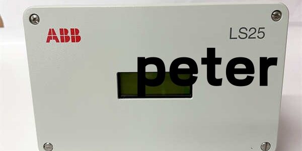
Product Core Brief
- Model: AO2000-LS25 (short name LS25)
- Brand: ABB Measurement & Analytics
- Series: Advance Optima AO2000 Modular Gas Analyzer Platform
- Core Function: Performs non-contact cross-stack gas concentration measurement via TDLAS laser spectroscopy for stack, furnace and pipeline process monitoring.
- Product Type: Split in-situ tunable diode laser absorption spectroscopy gas analyzer
- Key Specs: 0.5–6 m optical path | Class 1/1M eye-safe laser | ATEX / IECEx Zone 2 certified | IP66 transmitter/receiver housingsNote: Active production OEM equipment, new original surplus stock available; integrates with AO2000 central controller via Ethernet.
Key Technical Specifications
- Measurement principle: Tunable Diode Laser Absorption Spectroscopy (TDLAS), single isolated absorption line, zero cross-sensitivity to interfering gases
- Measurable species: O₂, NH₃, CO, CO₂, CH₄, H₂O, HCl, H₂S, HF, NO, NO₂
- Optical path range: 0.5 m minimum to 6 m maximum cross-stack distance
- Response speed: T90 < 1 second for fast dynamic concentration tracking
- Linear deviation: ≤ 1 % of full measurement span
- Repeatability: ≤ 0.25 % of full span
- Zero drift: ≤ 1 ppm or 1 % of span over 24 hours
- Laser safety: IEC 60825-1 Class 1 standard; O₂ variants post-Oct 2017 rated Class 1M
- Enclosure rating: Transmitter and receiver IP66 coated aluminum housings
- Power supply options: Main unit 85–264 V AC 50/60 Hz; transmitter direct input 18–32 V DC, max 20 W draw
- Purge requirements: Dry oil-free air or nitrogen; standard variant min 11 L/min purge flow
- Process pressure tolerance: Standard optical windows withstand up to 5 bar absolute pressure
- Operating ambient: -20 °C to +55 °C continuous duty; storage -20 °C to +55 °C
- Communication interfaces: Ethernet (CAT5 outdoor UV-resistant cable, max 25 m run), RS232 service port, 4–20 mA analog input for external pressure/temp sensors
- Hazardous certifications: ATEX II 3G Ex nA IIC T4 Gc Zone 2, IECEx, CSA Class I Div 2 Groups A-D
- Mechanical split design: Separate laser transmitter unit, photodetector receiver unit, external power supply cabinet
- Total assembly weight: 3.6 kg combined transmitter + receiver set
Product Introduction
This split cross-stack laser analyzer is a field-mounted measurement device built to pair with the AO2000 central analysis controller for continuous industrial emissions and process gas monitoring. It mounts directly to DN50 flanges on furnace stacks, boiler ducts and petrochemical pipelines without extractive sample conditioning hardware.Single-line TDLAS spectral filtering eliminates cross-gas interference that plagues NDIR and UV photometric analyzers, holding measurement error below 1% full span even with high background dust and mixed flue gas compositions. Built-in continuous purge gas flow keeps optical windows clean to cut monthly maintenance intervals by 70% compared to extractive sampling systems.
QA & Testing SOP
- Incoming Inspection: Cross-reference serial numbers against ABB analytical spare part databases. Inspect aluminum housing coating for scratches, purge port fittings for seal integrity, LCD display functionality and full LED status indicators. Reject units with punctured factory anti-static vacuum packaging to filter counterfeit inventory.
- Live Testing: Mount the transmitter/receiver pair on a 3 m optical test bench paired with an AO2000 central unit simulator. Run continuous 24-hour cyclic concentration sweep testing with certified calibration gas while logging stable AC/DC supply via Fluke 115 multimeter. Simulate purge gas loss, window contamination and temperature swing to validate auto-compensation and fault flag timing.
- Electrical Testing: Use a 500V Megger to measure insulation resistance between field hazardous circuit and controller communication wiring; pass threshold set at ≥10 MΩ. Inject 50Hz differential ground-loop noise to confirm no erratic concentration output drift.
- Firmware/Config Backup: Record factory default optical path length and gas species preset values via AO2000 PC service software. Capture high-resolution photos of purge port pinouts, Ethernet terminal block and flange mounting dimensions for field commissioning reference.
- Final QC & Packaging: Cap all purge gas inlet/outlet ports with plastic dust plugs, wrap transmitter/receiver optics in static-shield film. Place full split assembly inside foam-lined anti-static shipping crate, affix a dated QC pass label before sealing in original factory outer carton.
Installation Pitfalls & Guide
❗Firmware Rev Mismatch Risk: central controller firmware older than v4.1.0 lacks register mapping for TDLAS cross-stack path length compensation logic. Post-installation, the DCS will show persistent concentration offset drift and intermittent ETHERNET COMM LOSS alarms. Remediation: Flash matching firmware revision to the central unit before flange mounting.❗Purge Gas Contamination Risk: Purge air failing DIN ISO 8573-1 Class 533 quality carries oil or particulate residue that coats optical windows within 72 hours, disabling accurate readings. Install inline filter regulators upstream of all purge supply lines per datasheet specs.❗Wiring Incompatibilities: Unshielded Ethernet cabling introduces RF interference into laser signal circuits, creating ±0.8% full span measurement drift near variable frequency drives. Use UV-resistant double-sheathed CAT5 outdoor cable with single-point chassis ground at the control cabinet, follow 0.8 N·m torque specs for terminal screws.❗Power Draw Changes: A degraded 24 V DC auxiliary supply with less than 20% current headroom cannot support the transmitter plus external pressure/temperature analog sensors during cold startup, triggering repeated Ethernet handshake resets and total gas data loss. Recalculate total field load before mounting the assembly.❗ESD Dangers: Ungrounded handling exposes laser diode and photodetector analog traces to static discharge from dry plant ambient air. Field records show unprotected handling burns optical signal circuits; full boiler emissions compliance downtime labor cost exceeds $2,150. Remediation: Place anti-static mat under the stack flange mounting area, wear grounded wrist strap, touch bare metal process pipe ground for 3 seconds before handling transmitter/receiver electronics.
4-step replacement guide
- Pre-install: Lock out and tag stack duct high-temperature process flow; isolate and vent purge gas supply. Photograph existing flange alignment, purge piping layout and Ethernet cable pin assignments from the old split assembly.
- Removal: Close purge supply shutoff valve, unbolt DN50 flange fasteners, detach Ethernet and 24 V DC power wiring one cable at a time to avoid cross-circuit miswiring.
- Install: Mount new transmitter/receiver to matching stack flanges, reconnect purge gas piping and electrical harnesses, align optical beam path per ABB alignment tool procedure and lock flange fasteners to specified torque.
- Power-on Test: Restore purge gas flow first; confirm stable window purge pressure and full LED status illumination, connect certified calibration gas to validate linear concentration output before restoring full Ethernet communication and emissions data logging.
FAQ (Frequently Asked Questions)
Q: Can this split laser analyzer be hot-swapped while the central unit remains powered?A: No. The device maintains continuous Ethernet handshaking with the central controller; disconnecting live power creates voltage transients that corrupt process scan tables and can permanently damage the CPU board. Full lockout of field 24 V DC and purge gas supply is mandatory for replacement.Q: Does this analyzer carry original OEM factory warranty when purchased as new surplus?A: ABB factory warranty coverage follows analytical equipment lifecycle timelines. All surplus inventory passes full in-house bench QA testing and carries a 12-month internal stock replacement warranty, limited to manufacturing defects detected during validation testing.Q: Can LS22 serve as a direct drop-in replacement for the unit?A: DN50 flange mechanical fit only. LS22 supports a maximum optical path of 3 m and lacks built-in multi-species TDLAS compensation logic. Swapping without reworking stack mounting hardware and control logic limits usable cross-stack measurement range and disables multi-gas monitoring capability.Q: What minimum central controller firmware version enables full path length auto-compensation support?A: central unit firmware v4.1.0 or newer. Older builds lack register addresses for variable optical span correction, only returning uncompensated raw absorption values with large concentration offset error across different stack widths.Q: Will the analyzer retain gas species and path length configuration settings after power loss?A: Calibration and path length parameters store in non-volatile memory on the transmitter mainboard; no re-configuration of core measurement ranges is required post power cycle. Full span calibration with certified gas is still recommended after hardware replacement.Q: Is the unit compatible with System 800xA AC800M DCS controllers without the central cabinet?A: No. The LS25 relies on the central processing unit for concentration math conversion and DCS bus communication. Direct wiring to AC800M analog input cards only returns raw absorption signals with no standardized gas concentration scaling.Q: Can the analyzer operate without continuous purge gas flow?A: Short-term operation (max 15 minutes) is permitted for troubleshooting only. Extended operation without purge allows flue dust and condensate to adhere to optical windows, causing irreversible measurement drift and permanent coating damage to laser lenses.




