
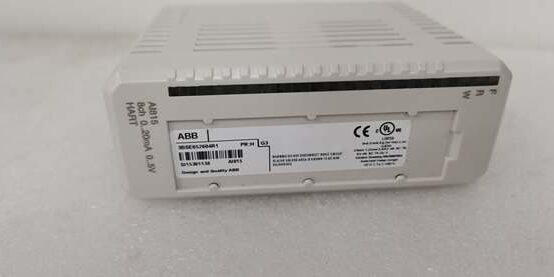
Product Core Brief
- Model: AI830A, OEM Article Code 3BSE040662R1
- Brand: ABB
- Series: S800 Distributed I/O for AC800M / System 800xA / Freelance DCS
- Core Function: Acquires 8 independent 3-wire RTD resistance signals, linearizes temperature data and transmits converted values to the DCS controller via backplane fieldbus.
- Product Type: Rack slide-in RTD analog input I/O module
- Key Specs: 8 configurable RTD channels | 14-bit A/D resolution | 500 VAC group dielectric isolationNote: Active OEM spare, new original surplus stock available; no HART or thermocouple input support.
Key Technical Specifications
- Operating supply: 24 V DC ±10 %, typical draw 50 mA, max power dissipation 1.6 W
- Supported sensors: Pt100 Euro/US, Ni100, Ni120, Cu10, passive resistive potentiometers; only 3-wire wiring per channel
- A/D hardware: 14-bit resolution with dedicated on-board linearization for temperature units (°C / °F)
- Full 8-channel scan cycle: 150 + (95 × active channel count) ms refresh rate
- Measurement accuracy: ±0.15 °C full scale at 25 °C ambient, temperature drift ≤40 ppm/°C
- Galvanic isolation: Single group isolation between field sensors and backplane logic, 500 VAC 1-minute dielectric withstand
- Noise rejection: >120 dB CMRR at 50/60 Hz mains frequency
- Built-in diagnostics: Open-circuit wire break, short-circuit and sensor ground fault detection per channel
- PCB coating: ISA-S71.04 G3 grade conformal coating for mild corrosive cabinet atmospheres
- Status indicators: Individual LED per channel, global POWER, RUN and MODULE FAULT diagnostic lamps
- Mechanical form: Standard S800 slide-in card, hot-swap certified to IEC 61131-2; compatible with TU810, TU812, TU814, TU830 termination units
- Operating ambient: 0 °C to +55 °C continuous duty; compact MTU racks limited to 0–40 °C
- Storage range: -40 °C to +70 °C, non-condensing 5–95 % relative humidity
- Physical dimensions: 45 mm W × 119 mm H × 111 mm D (including terminal connector)
- Net weight: 0.22 kg
Product Introduction
This I/O card is a dedicated resistance temperature detector acquisition component built exclusively for S800 I/O racks paired with AC800M and 800xA DCS controllers. It handles bearing, vessel and stack temperature monitoring across thermal power, pulp and chemical process plants.Group galvanic isolation blocks common-mode noise from nearby variable frequency drives, holding steady-state temperature reading deviation below 0.15 °C during large motor load transients. On-chip RTD linearization eliminates manual conversion logic programming inside the DCS controller, cutting tag configuration workload for field engineers.
QA & Testing SOP (Transparency Building)
- Incoming Inspection: Cross-reference serial numbers and 3BSE part code against ABB S800 spare part databases. Inspect conformal coating for delamination, terminal block spring tension and full 8-channel LED functionality. Reject units with torn factory anti-static packaging to filter counterfeit inventory.
- Live Testing: Seat the module in an S800 MTU test rack paired with an AC800M PM865 controller simulator. Run continuous 24-hour cyclic scan testing across all channels while logging stable 24VDC supply with a Fluke 115 multimeter. Simulate open RTD leads, sensor short-circuit and grounded probe faults to validate diagnostic flag timing.
- Electrical Testing: Use a 500V Megger to measure insulation resistance between field channel group and backplane logic; pass threshold set at ≥10 MΩ. Inject 50Hz differential ground-loop noise to confirm no false wire-break fault triggers.
- Firmware/Config Backup: Record factory default RTD type preset values via Control Builder M engineering software. Capture high-resolution photos of terminal pin labeling for field commissioning reference.
- Final QC & Packaging: Fit plastic dust caps over the front terminal header. Place the card inside foam-lined anti-static shielding bag, affix a dated QC pass label before sealing in original factory carton.
Installation Pitfalls & Guide (Engineer to Engineer)
❗Firmware Rev Mismatch Risk: AC800M controller firmware older than v5.3.2 lacks register mapping for 3-wire lead resistance compensation logic. Post-replacement, the DCS will show skewed temperature offsets and intermittent AI COMM LOSS alarms. Remediation: Flash matching firmware revision to the main controller before rack insertion.❗Wiring Mode Restriction Risk: The unit only supports 3-wire RTD connections. Installing 2-wire sensors without adding a dedicated compensation lead creates permanent temperature drift exceeding ±2 °C full scale. Always match field sensor wiring to the module’s 3-terminal pin layout.❗Wiring Incompatibilities: Unshielded field wiring introduces mains interference into resistance inputs, creating ±0.3 °C reading drift. Use OEM shielded twisted pair cable with single-point chassis ground at the rack terminal bar, follow 0.8 N·m torque specs for terminal screws.❗Backplane Power Draw Changes: A degraded rack 24VDC supply with less than 20% current headroom cannot support the unit plus multiple analog output cards during controller cold startup, triggering repeated backplane resets and total temperature data loss. Recalculate total rack load before swapping the card.❗ESD Dangers: Ungrounded handling exposes resistance measurement analog traces to static discharge from dry control room air. Field records show unprotected handling burns input signal circuits; full boiler/turbine unit downtime labor cost exceeds $1,540. Remediation: Place anti-static mat under the rack, wear grounded wrist strap, touch bare rack chassis ground for 3 seconds before handling the PCB.
4-step replacement guide
- Pre-install: Lock out and tag rack 24VDC auxiliary power for high-EMI sites; pause Profibus fieldbus communication if performing live hot-swap. Photograph terminal wiring layout and existing channel RTD type assignments from the old unit.
- Removal: Release the rack slide latch, pull the old card free and disconnect terminal wiring one channel at a time to avoid cross-channel miswiring.
- Install: Transfer 3-wire RTD harness to the new unit’s terminal header, slide the card fully into the MTU rack slot and lock the slide latch.
- Power-on Test: Restore 24VDC auxiliary power first; verify all channel LEDs activate correctly, connect a precision RTD simulator to confirm accurate linearized temperature readings before resuming full DCS fieldbus communication.
FAQ (Frequently Asked Questions)
Q: Can this module be hot-swapped while the rack remains powered?A: Yes, the hardware carries official ABB hot-swap certification for standard low-EMI control rooms. For cabinets housing medium voltage drives or high-frequency VFDs, lock out auxiliary power first to avoid backplane data corruption from voltage transients.Q: Does this card carry original OEM factory warranty when purchased as new surplus?A: ABB factory warranty coverage follows component lifecycle timelines. All surplus inventory passes full in-house QA testing and carries a 12-month internal stock replacement warranty, limited to manufacturing defects detected during bench validation.Q: Can AI835A serve as a direct drop-in replacement for the module?A: Mechanical rack fit only. AI835A is an 8-channel thermocouple/mV input board with no RTD excitation circuitry. Swapping without reworking field sensor wiring and DCS tag logic will disable all plant resistance temperature monitoring loops.Q: What minimum controller firmware version enables full 3-wire RTD lead compensation support?A: AC800M controller firmware v5.3.2 or newer. Older builds lack register addresses for lead resistance correction, only returning uncompensated raw resistance values with large temperature offset error.Q: Will the unit retain RTD type and wiring mode settings after power loss?A: No configuration data stores on-board. All channel RTD parameters reside in the controller’s non-volatile memory. No re-calibration of the device itself is needed post-swap.Q: Is the unit compatible with Symphony Plus SD Series DCS racks?A: No. The module uses the proprietary Profibus backplane bus, which is electrically incompatible with Symphony HN800 I/O rack architecture and cannot be cross-mounted.Q: Can I connect 4-wire RTD sensors directly to the terminals?A: Direct connection is unsupported. 4-wire sensors must be terminated to a TU81x series external termination unit to split compensation leads; direct wiring to the module creates unresolved lead resistance measurement error.




