
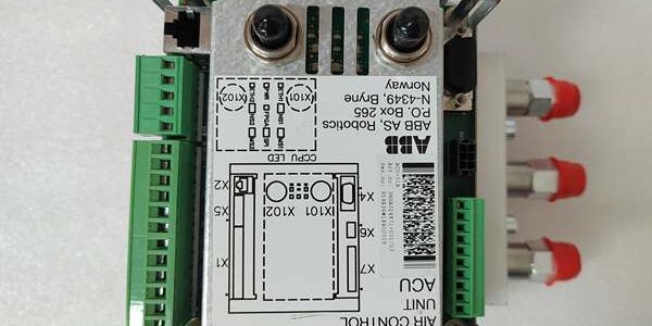
Product Core Brief
- Model: ACU-01B
- Brand: ABB
- Series: ACS medium voltage drive auxiliary control subassembly
- Core Function: Monitors cabinet cooling fans, thermal interlocks, door safety switches and auxiliary contact logic for MV drive power stacks.
- Product Type: Cabinet auxiliary control printed circuit board
- Key Specs: 24VDC supply | Multi-channel digital DI/DO | Cabinet thermal fault interlock logicNote: Discontinued EOL OEM spare, limited new surplus stock available.
Key Technical Specifications
- Operating supply: 24 V DC ±10 %, maximum power draw 3.8 W
- Digital input channels: 8 sink-type DI for door interlocks, thermal sensors, fan feedback
- Digital output channels: 6 transistor DO for fan enable, fault relay actuation
- Galvanic isolation: 500 VAC group isolation between field wiring and internal logic
- PCB coating: Full acrylic conformal coating for dust, humidity and light corrosive fume resistance
- Status indicators: Individual LED per DI/DO channel, global POWER and FAULT lamps
- Mechanical form: Slide-in small Eurocard for ACS drive auxiliary rack, no hot-swap capability
- Operating ambient: -20 °C to +70 °C, linear performance derating above 65 °C
- Storage range: -40 °C to +85 °C, non-condensing 5–95 % relative humidity
- Dimensions: 186 mm L × 34 mm W × 28 mm D
- Net weight: 0.21 kg
Product Introduction
This unit is a dedicated auxiliary logic board built exclusively for ABB medium voltage drive cabinets. It aggregates all low-voltage cabinet safety and cooling signals before forwarding status data to the main drive CPU.Its integrated interlock circuit forces a controlled drive shutdown if fans fail, cabinet temperature exceeds threshold or cabinet doors open mid-operation, preventing catastrophic overheating of power semiconductors.
QA & Testing SOP (Transparency Building)
- Incoming Inspection: Cross-reference serial numbers against ABB ACS spare part databases. Inspect conformal coating for cracks, terminal block spring tension and full LED functionality. Discard units with broken OEM anti-static packaging to filter counterfeit stock.
- Live Testing: Mount the device in an ACS auxiliary test rack paired with a signal simulator. Run a continuous 24-hour cyclic test toggling all DI/DO channels while logging stable 24VDC supply via Fluke 115 multimeter. Simulate fan loss and overtemperature triggers to validate interlock shutdown sequence.
- Electrical Testing: Use a 500V Megger to measure insulation resistance between field channels and internal logic; pass threshold set at ≥10 MΩ. Inject differential ground-loop noise to confirm no false interlock trips.
- Firmware/Config Backup: Record factory interlock threshold parameters via DriveWindow software. Capture high-resolution photos of all on-board DIP jumpers and terminal pin labels for field commissioning reference.
- Final QC & Packaging: Cap all terminal blocks with plastic dust covers. Place the PCB inside foam-lined anti-static shielding bag, affix a dated QC pass label before sealing in original factory carton.
Installation Pitfalls & Guide (Engineer to Engineer)
❗Firmware Rev Mismatch Risk: Main drive CPU firmware older than v5.1.2 lacks register mapping for the unit’s multi-fan monitoring logic. Post-replacement, the drive will throw persistent CABINET INTERLOCK LOSS alarms and ignore fan fault signals. Remediation: Flash matching firmware revision to the main controller before rack installation.❗DIP Switch/Jumper Errors: On-board jumpers set fan quantity and thermal trip thresholds; factory preset values match standard ACS frames only. Always photograph jumper positions on the old board before removal and replicate exact placements; misconfiguration triggers unplanned drive trips under normal operating temperature.❗Wiring Incompatibilities: Generic unshielded twisted pair field wiring introduces 50Hz mains noise into DI channels, creating random door open fault flags. Use OEM shielded control cable with single-point chassis ground at the drive cabinet terminal bar, follow torque specs for terminal screws.❗Power Draw Changes: A degraded rack 24VDC auxiliary supply with less than 20% current headroom cannot support this unit plus multiple GDU boards during drive startup, triggering repeated auxiliary power resets and lost interlock signals. Recalculate total rack load before swapping the part.❗ESD Dangers: Ungrounded handling exposes analog sensing traces to static discharge from dry workshop air. Field records show unprotected handling burns input signal circuits; full drive downtime labor cost exceeds $1,450. Remediation: Use anti-static mat under the cabinet, wear grounded wrist strap, touch bare chassis ground for 3 seconds before handling the PCB.
4-step replacement guide
- Pre-install: Lock out and tag all cabinet AC and 24VDC auxiliary power; discharge DC link fully. Photograph old unit jumper positions and field wiring layout.
- Removal: Release rack slide latch, pull the old card free and disconnect terminal wiring harness one channel at a time.
- Install: Transfer wiring harness to the new unit’s terminal block, match photographed jumper settings, slide the PCB fully into the auxiliary rack slot and lock the latch.
- Power-on Test: Restore 24VDC auxiliary power first; verify all channel LEDs activate correctly, simulate a fan fault to confirm the drive registers the interlock alarm before restoring main high voltage power.
FAQ (Frequently Asked Questions)
Q: Can this unit be hot-swapped while the drive cabinet remains powered?A: No. It shares a common 24VDC backplane with core measurement hardware. Removing it live creates voltage transients that can damage the main CPU’s signal input ports, leading to permanent controller failure. Full lockout of auxiliary power is mandatory for replacement.Q: Does this board carry a manufacturer warranty when purchased as new surplus?A: Original OEM factory warranty expired at production end-of-life. All surplus inventory passes full in-house QA testing and carries a 12-month internal stock replacement warranty, limited to verified manufacturing defects found during bench testing.Q: Can ACU-01A serve as a direct drop-in replacement for this device?A: Partial mechanical fit only. The older ACU-01A lacks dual-fan fault grading logic and extra thermal DI channels. Swapping without reworking cabinet wiring and re-tuning drive interlock parameters will result in incomplete fault monitoring.Q: What firmware version is required for full compatibility with the unit’s feature set?A: Drive main CPU firmware v5.1.2 or newer. Older builds lack register addresses for multi-stage cabinet thermal pre-alarm signals, only reporting a generic cabinet fault without granular diagnostic data.Q: Will the unit retain its interlock threshold settings after power loss?A: No calibration data is stored on-board. All fan count and temperature trip values reside in the main drive controller’s non-volatile memory. No re-calibration of the device itself is needed post-swap.Q: Is this unit compatible with ACS6000 high-power water-cooled drives?A: No. The board’s DI/DO channel count and interlock logic are calibrated for air-cooled ACS1000/ACS2000 frames. Water-cooled ACS6000 cabinets use a separate auxiliary control assembly with different signal pinout definitions.Q: How long is the expected service life of the conformal coating in a cement plant cabinet environment?A: Under continuous high-dust, moderate flue gas exposure, the coating maintains full insulation performance for roughly 7 years. Annual visual inspection of the PCB surface is recommended to track coating degradation.




