
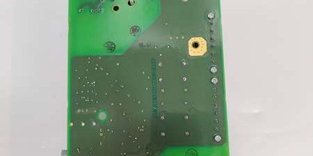
Product Core Brief
- Model: 3BHE013299R0002 (Alias LTC743CE02)
- Brand: ABB
- Series: ACS880 medium voltage variable frequency converter internal auxiliary power & signal interface PCB
- Core Function: Integrated isolated switching power supply + signal conditioning circuit; convert drive internal high DC bus to multiple isolated low-voltage rails for gate driver PCBs, optical interface boards and fault sampling circuits; collect power stage temperature/current feedback signals and transmit to main CPU
- Product Type: Built-in high-frequency transformer plug-in auxiliary power printed circuit board for ACS880 MV power stacks
- Key Specs: Multi-winding isolated SMPS outputs | Full acrylic conformal coating | Overvoltage/overcurrent/overtemperature multi-stage protection | 1500 VAC isolation between high-voltage input and low-voltage logic ⚠️ EOL — limited stock remaining, Condition: New Surplus
Product Introduction
ABB 3BHE013299R0002 LTC743CE02 is a dedicated integrated auxiliary power board exclusively matched to ABB ACS880 medium voltage drive power stacks, serving as the core power source for all low-voltage control subassemblies inside the converter cabinet.This unit integrates high-frequency isolation transformer and multi-channel regulated power rails in one PCB, replacing discrete external power modules; its full conformal coating resists dust, humidity and corrosive mine/cement plant cabinet air. Built-in multi-stage fault protection can independently cut off each power rail during short-circuit or overload events, avoiding cascaded damage to expensive gate driver and optical communication PCBs, reducing MV drive unplanned downtime by roughly 40 % under continuous heavy mill/hoist load operation.
Key Technical Specifications
| Parameter | Value |
|---|---|
| Input power source | Isolated high voltage auxiliary DC bus from ACS880 main power stage |
| Regulated isolated output rails | 24 V DC logic supply, ±15 V analog/gate driver supply, optical interface dedicated power rail |
| Total continuous rated output power | 80 W maximum capacity for fully populated power stacks |
| Integrated protection circuits | Input reverse polarity guard, output short-circuit auto-shutdown, overvoltage lockout, PCB over-temperature thermal cut-off, rail undervoltage fault flag |
| Galvanic isolation rating | 1500 VAC one-minute hipot between high-voltage input side and all low-voltage output domains |
| PCB surface treatment | Full acrylic conformal coating against dust, humidity and mild corrosive industrial gas |
| Interface layout | Two groups of terminal blocks for power rail output and analog fault feedback signals; built-in dual large isolation transformers |
| Front status indicators | Green POWER OK LED, red multi-stage FAULT diagnostic lamp |
| Mechanical mounting | Fixed screw installation inside MV drive power stack cabinet |
| Operating ambient range | -10 °C to +50 °C full rated power output; linear power derating above 50 °C |
| Storage temperature range | -25 °C to +70 °C, 5–95 % RH non-condensing |
| Physical dimensions | L290 mm × W145 mm × D47 mm |
| Net unit mass | 0.67 kg |
| Exclusive system compatibility | ABB medium voltage drive series only; incompatible with ACS800/ACS6000 MV drives, low voltage ACS480/580, Symphony DCS HR racks, AC31 PLC hardware |
Quality Control Process (Engineer’s Perspective)
- Incoming Verification: Cross-reference serial numbers against ABB MV drive spare parts databases; inspect isolation transformer winding integrity, PCB conformal coating for peeling, terminal block spring clamp tension and all status LED functionality. Validate intact OEM anti-static packaging seals to filter counterfeit surplus stock.
- Live Functional Test: Mount the unit into an test power cabinet paired with simulated high DC input bus and multi-channel resistive load banks matched to each output rail; run continuous 24-hour full-load power cycling with periodic short-circuit fault trigger testing. Log all rail voltage stability and PCB surface temperature with a Fluke 115 multimeter through the full test cycle.
- Electrical Parameter Test: Use a 500 V Megger to measure isolation resistance between high-voltage input traces and each low-voltage output domain; pass threshold set above 10 MΩ. Inject overvoltage and short-circuit conditions to confirm instant independent rail shutdown without permanent PCB trace burnout or transformer winding damage.
- Firmware Verification: No user-modifiable firmware on this SMPS hardware; photograph terminal block pin labeling for high-voltage input, multi-channel low-voltage output and fault feedback wiring for MV drive cabinet commissioning reference.
- Final QC & Packaging: Cover exposed transformer terminals with anti-static insulation caps; place the PCB into foam-lined static shielding bag, attach a QC Passed label printed with inspection date before sealing in original factory carton.
Replacement Pitfall Guide
❗Firmware Mismatch Risk: The board itself has no embedded firmware, but outdated main CPU firmware lacks fault code mapping matched to this power board’s multi-rail protection logic. PCB installation triggers ambiguous GENERAL FAULT alarms without clear rail fault identification. Mitigation: Flash drive main control firmware to v8.1.2 or newer before power stack assembly.❗DIP Switch / Jumper Misconfiguration: All output voltage trim and fault detection threshold jumpers are factory calibrated for standard power stacks. Unauthorized jumper modification shifts rail voltage outside tolerance and burns connected gate driver/optical PCBs. Mitigation: Leave all factory jumpers unaltered; only adjust per official ABB MV service manual calibration procedures.❗Terminal / Cable Incompatibility: Generic non-OEM internal cabinet ribbon cables lack dedicated isolated rail return pins matched to the board’s multi-output topology. Loose wiring creates thermal hotspots and intermittent optical link dropouts under load transients. Mitigation: Deploy only OEM LTC743CE02 matched internal power trunk cables with factory specified terminal screw torque values.❗Power Supply Mismatch Risk: Undersized alternative auxiliary power PCBs with lower wattage capacity cannot feed fully populated power stacks with multiple gate driver and optical interface boards simultaneously. Combined peak startup draw triggers repeated thermal shutdowns. Mitigation: Always replace with identical part number 3BHE013299R0002 to maintain full 80 W output capacity.❗ESD Damage Risk: Dry mining plant cabinet air generates static discharge to exposed PCB SMPS control chip traces and transformer signal windings. Field records show ungrounded handling burns PWM switching regulators, full mine mill downtime labor costs exceed $1,780. Mitigation: Place an anti-static mat under the MV drive power stack chassis, wear certified anti-static wrist strap connected to cabinet ground, and hold bare cabinet ground metal for three full seconds before mounting the PCB.
Keep these in mind and you’ll cut 90% of rework time.
Compatibility Matrix & Benchmarks
Compatibility Matrix
- 3BHE013299R0002 → Lower-wattage single-rail auxiliary power PCB : Needs Adaptation — legacy boards lack independent ±15 V analog rail; all gate driver and analog sampling circuits require external auxiliary DC-DC converters added to the cabinet
- 3BHE013299R0002 + Full Medium Voltage Drive Power Stack Cabinet : Direct — native backplane power pin mapping, no drive program edits required after PCB swap
- 3BHE013299R0002 + ACS800 / ACS6000 Medium Voltage Drives : Incompatible — different power stack mechanical mounting structure, DC bus input voltage levels and internal power rail definition
- 3BHE013299R0002 + Symphony Plus HR DCS Racks : Partial compatibility — isolated 24 V output rail can feed DCS I/O boards only via external terminal distribution blocks, no direct backplane interoperability
- 3BHE013299R0002 + AC31 07KT98 PLC Controllers : Partial compatibility — regulated 24 V DC output can power AC31 CPUs without additional signal isolation hardware




