
Product Core Brief
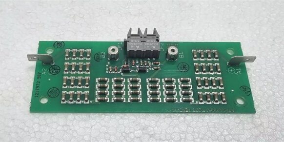
- Model: 3BHE009017R0102 (Alias XVC724BE102, VLSCD signal control board)
- Brand: ABB
- Series: Symphony Plus Harmony HR rack distributed control system interface board, compatible with 800XA & AC500 platform signal conversion
- Core Function: Real-time field signal conditioning, Modbus RTU gateway, turbine/generator excitation analog & discrete signal isolation; bridge Symphony backplane bus with external MV drives, excitation rectifiers and IED intelligent electronic devices
- Product Type: Standard slide-in Eurocard VLSCD printed circuit board for Symphony HR rack backplanes
- Key Specs: Mixed analog/digital multi-channel isolation | RS485 Modbus RTU dual communication | 24 V DC backplane supply | Full acrylic conformal coating | SIL2 functional safety certified ⚠️ EOL — limited stock remaining, Condition: New Surplus
Product Introduction
ABB 3BHE009017R0102 XVC724BE102 VLSCD is a universal signal interface Eurocard exclusively designed for ABB Symphony Plus Harmony HR DCS racks, widely deployed in thermal power, hydropower and metallurgy plant turbine control, generator excitation and boiler interlock cabinets.This unit integrates analog sampling, discrete DI/DO and Modbus communication in a single rack slot, replacing multiple separate signal conditioning modules to save cabinet space. Its multi-stage galvanic isolation and reinforced EMC filtering suppress severe electromagnetic interference from high-power excitation stacks and ACS MV variable frequency drives, cutting analog measurement drift and false protection trips by roughly 58 % under heavy unit load transients. The full conformal coating resists dust, humidity and flue gas corrosion for 24/7 continuous power plant operation. Compared to older single-function interface cards, it unifies drive communication and process signal acquisition logic to simplify DCS wiring architecture.
Key Technical Specifications
| Parameter | Value |
|---|---|
| Operating supply | 24 V DC ±20 %, powered via Symphony HR rack backplane; max 10 W power consumption |
| Channel configuration | 2 × configurable 4–20 mA analog input; 16 × 24 V DC sinking digital output; RS485 Modbus RTU master/slave port |
| Channel isolation rating | 1500 VAC one-minute hipot isolation between field wiring and internal DCS backplane logic |
| Communication interfaces | 1. Internal Symphony proprietary Harmony backplane high-speed data bus; 2. External RS485 Modbus RTU (9.6 kbps ~ 115.2 kbps) |
| PCB surface protection | Full industrial acrylic conformal coating for dust, humidity and mild corrosive flue gas resistance |
| Integrated protection circuits | Per-channel short-circuit current limiting, input overvoltage lockout, reverse power supply guard, supply undervoltage fault flag |
| Front status indicators | Per-channel signal LED, global POWER, BACKPLANE BUS, MODBUS COMM, multi-stage FAULT diagnostic lamps |
| Mechanical form factor | Standard Harmony HR rack slide-in Eurocard horizontal mounting |
| Operating ambient range | -25 °C to +70 °C full rated signal precision; linear performance derating above 65 °C |
| Storage temperature range | -40 °C to +85 °C, 5–95 % RH non-condensing |
| Physical dimensions | W33 mm × H233 mm × D132 mm |
| Net unit mass | 0.10 kg |
| Exclusive system compatibility | ABB Symphony Plus / Harmony HR DCS racks, compatible with 800XA & AC500 PLC signal interconnection; incompatible with standalone AC31 PLC, S800 standalone I/O, ACS low/medium drive internal power stack hardware |
Quality Control Process
- Incoming Verification: Cross-reference serial numbers against ABB Symphony DCS spare parts databases; inspect edge connector gold plating for oxidation, PCB conformal coating integrity, all analog/digital channel and communication LED functionality, terminal block spring clamp tension. Validate intact OEM anti-static packaging seals to filter counterfeit surplus stock.
- Live Functional Test: Insert the unit into a Symphony Harmony HR test rack paired with DCS CPU simulator, calibrated 4–20 mA signal sources and Modbus RTU MV drive simulator; run continuous 24-hour cyclic analog sampling, discrete channel switching and bidirectional bus data exchange. Log stable 24 V backplane voltage and PCB surface temperature with a Fluke 115 multimeter through the full test cycle.
- Electrical Parameter Test: Use a 500 V Megger to measure isolation resistance between all isolated circuit domains; pass threshold set above 10 MΩ. Inject differential ground-loop voltage and per-channel short-circuit faults to confirm independent channel current limiting without full board power reset.
- Firmware Verification: Read and record factory VLSCD interface firmware revision via ABB Symphony Composer diagnostic tool; photograph edge connector and field terminal block pin labeling for analog transmitters, Modbus bus and backplane wiring for power plant cabinet commissioning reference.
- Final QC & Packaging: Wipe PCB surfaces with anti-static cloth; place the Eurocard into foam-lined static shielding bag, attach a QC Passed label printed with inspection date before sealing in original factory carton.
Replacement Pitfall Guide
❗Firmware Mismatch Risk: Older Symphony Plus controller firmware revisions lack register mapping matched to this board’s multi-channel Modbus layout. Card insertion triggers persistent COMM LOSS and frozen analog value faults during turbine load transients. Mitigation: Upgrade DCS main controller firmware to v6.2.1 or newer before rack installation.❗DIP Switch / Jumper Misconfiguration: All Modbus slave address, signal range and bus termination jumpers are factory preset. Unauthorized jumper modification causes bus collision or clipped analog measurement signals. Mitigation: Photograph jumper positions on the old card before removal and replicate exact settings on the replacement unit; do not alter factory calibration jumpers without official ABB service documentation guidance.❗Terminal / Cable Incompatibility: Unshielded field and Modbus cables lack twisted-pair EMC drain wires matched to the board’s differential analog front-end. Long unshielded field wiring introduces mains-coupled noise and fluctuating steam flow/turbine voltage feedback values. Mitigation: Deploy only OEM shielded twisted-pair field cables with single-point shield grounding at the DCS cabinet terminal bar.❗Power Supply Mismatch Risk: Degraded Symphony rack backplane 24 V DC bus with insufficient current capacity cannot feed a fully populated HR rack with multiple VLSCD boards. Combined peak communication startup draw triggers repeated rack power reset events. Mitigation: Verify rack backplane power supply capacity with 20 % current headroom above total combined rack module load before replacement.❗ESD Damage Risk: Dry power plant control room air generates static discharge to exposed edge connector and analog op-amp traces. Field records show ungrounded handling burns Modbus transceivers and analog sampling circuits, full generator unit downtime labor costs exceed $1,900. Mitigation: Place an anti-static mat under the DCS rack chassis, wear certified anti-static wrist strap connected to cabinet ground, and hold bare cabinet ground metal for three full seconds before extracting/seating the Eurocard PCB.
Keep these in mind and you’ll cut 90% of rework time.
Compatibility Matrix & Benchmarks
Compatibility Matrix
- 3BHE009017R0102 → Legacy single-bus Symphony interface PCB : Needs Adaptation — older boards lack dual analog/Modbus circuits; all drive excitation communication logic must be re-mapped and split across multiple rack slots
- 3BHE009017R0102 + Symphony Plus Harmony HR DCS Racks : Direct — native backplane register mapping, no major DCS project logic edits required after PCB swap
- 3BHE009017R0102 + ABB ACS800/ACS880 Medium Voltage Drives : Partial compatibility — Modbus RTU port can directly link to MV drive control boards without extra protocol converters
- 3BHE009017R0102 + AC31 07KT98 PLC Controllers : Incompatible — AC31 CS31 serial bus cannot interface with Symphony proprietary Harmony rack backplane communication
- 3BHE009017R0102 + S800 AI/DO Process I/O Modules : Partial compatibility — analog 4–20 mA signals can cross-connect via terminal blocks, no direct backplane bus interoperability




