
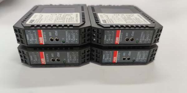
Product Core Brief
- Model: 1SVR011700R0000 (CC-E/STD)
- Brand: ABB
- Series: CC-E analog signal isolation converter range
- Core Function: Isolate, scale and convert industrial voltage/current analog signals between field transmitters and DCS/PLC I/O racks
- Product Type: Compact DIN rail 3-way isolated signal conditioning unit
- Key Specs: Single channel | 3-way galvanic isolation | DIP-switch configurable V/mA I/O ⚠️ EOL — limited stock remaining, Condition: New Surplus
Product Introduction
ABB 1SVR011700R0000 is a universal isolation amplifier built to break ground loops between field transmitters and control system analog inputs.This unit outperforms single-range fixed converters by supporting four selectable input and output signal sets; front-mounted trim pots allow on-site gain and offset calibration without bench test gear, cutting field commissioning time by roughly 30 % for distributed tank and pump measurement loops.
Key Technical Specifications
| Parameter | Value |
|---|---|
| Channel count | 1 isolated analog input/output channel |
| Supported input signal ranges | 0–5 V, 0–10 V, 0–20 mA, 4–20 mA (DIP switch selectable) |
| Supported output signal ranges | 0–5 V, 0–10 V, 0–20 mA, 4–20 mA (DIP switch selectable) |
| Isolation topology | 3-way isolation: Field Input / Supply / Control Output |
| Dielectric isolation strength | 2500 VAC one-minute withstand |
| Operating supply | 24 V DC ± 10 %, 45 mA typical current draw |
| Calibration controls | Front panel gain and offset trim potentiometers |
| Status indicator | Single green LED to confirm active 24 V DC supply |
| Mechanical mounting | TS35 standard DIN rail horizontal installation |
| Housing dimensions | W22.5 mm × H75 mm × D107 mm |
| Net unit mass | 0.088 kg |
| Operating ambient range | -20 °C to +60 °C full rated conversion accuracy |
| Storage temperature | -40 °C to +70 °C, non-condensing 5–95 % RH |
| Compliance | RoHS, CE certified for industrial control cabinets |
Quality Control Process (Engineer’s Perspective)
- Incoming Verification: Cross-reference serial numbers to ABB CC-E spare parts databases; inspect side DIP switch travel, front potentiometer smooth rotation, LED functionality, and terminal screw spring tension. Validate intact OEM anti-static packaging seals to filter counterfeit surplus stock.
- Live Functional Test: Mount the unit to a DIN rail test bench paired with a calibrated mA/V signal source and precision load resistor; cycle all four DIP switch input/output range combinations for a continuous 24-hour run. Log stable 24 V supply and converter temperature with a Fluke 115 multimeter through the full cycle.
- Electrical Parameter Test: Use a 500 V Megger to measure isolation resistance across all three isolated domains; pass threshold set above 10 MΩ. Inject simulated ground loop differential voltage to confirm zero measurement offset drift on output signals.
- Firmware Verification: No programmable firmware on the unit; photograph side DIP switch layout and document factory default 4–20 mA input / 4–20 mA output configuration for commissioning reference.
- Final QC & Packaging: Wipe PCB surfaces with anti-static cloth; place the unit in foam-lined static shielding bag, attach a QC Passed label printed with inspection date before sealing in original factory carton.
Replacement Pitfall Guide
❗Firmware Mismatch Risk: Not applicable; the unit has no software firmware. Mismatch risk comes from incompatible signal range DIP settings, not controller code.❗DIP Switch / Jumper Misconfiguration: The unit ships factory-set for 4–20 mA input and output. Voltage transmitter wiring with unadjusted DIP switches yields clipped, non-linear scaled values in the DCS. Mitigation: Photograph DIP switch positions on the old unit and reselect matching input/output signal ranges before connecting field transmitters.❗Terminal / Cable Incompatibility: Unshielded field sensor cables lack drain wire grounding matched to the unit’s isolation front-end. Long unshielded runs introduce EMI noise and signal jitter. Mitigation: Deploy only twisted-pair shielded transmitter cables with single-point shield grounding at the converter cabinet terminal bar.❗Power Supply Mismatch: A low-wattage 1 A auxiliary supply cannot feed a DIN rail populated with multiple of these signal converters plus analog I/O modules. Combined steady-state draw exceeds the supply continuous rating. Mitigation: Size cabinet power supplies with 20 % current headroom above total combined isolation converter and I/O load.❗ESD Damage: Dry plant control room air generates static discharge to exposed DIP switch and terminal PCB traces. Field records show ungrounded handling burns input signal op-amps, full measurement skid downtime labor costs exceed $980. Mitigation: Place an anti-static mat under the DIN rail assembly and hold bare cabinet ground metal for three full seconds before sliding the unit onto the rail.
Keep these in mind and you’ll cut 90% of rework time.
Compatibility Matrix & Benchmarks
Compatibility Matrix
- 1SVR011700R0000 → Single-range CC-E converters : Needs Adaptation — fixed-range units lack multi-signal DIP switches, all transmitter wiring and DCS scaling blocks require full rework
- 1SVR011700R0000 + S800 AI810 / AI820 Analog I/O Modules : Direct — standard 4–20 mA / 0–10 V output matches native S800 analog input hardware
- 1SVR011700R0000 + AC31 07AI91 Multi-Type Analog Input Module : Direct — configurable output ranges align with AC31 universal analog channel support
- 1SVR011700R0000 + Freelance 2000 DAI04 Temperature Input Boards : Direct — signal scaling compatible, only cabinet rail mounting layout differs
- 1SVR011700R0000 + ACS Series Variable Frequency Drives : Incompatible — drive control logic uses proprietary serial communication instead of standard analog process signals




