
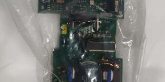
Product Core Brief
- Model: 1SFB527068D7084
- Brand: ABB
- Series: Low voltage variable frequency drive control PCB assembly
- Core Function: Process drive logic, motor feedback signals, and field communication for ABB general-purpose AC inverters
- Product Type: Plug-in main control printed circuit board for wall-mounted AC drives
- Key Specs: 12 V DC operating supply | RS485 + CANopen dual comm ports | Over-current/over-temperature onboard protection Condition: New Surplus
Product Introduction
ABB 1SFB527068D7084 is the primary logic board for mid-range ABB ACS series variable frequency drives, handling motor control algorithms and external field device communication on fan, pump, and compressor skids.This unit carries dual communication ports absent on basic drive PCBs; its integrated thermal monitoring cuts unplanned inverter shutdowns by roughly 35 % in high-ambient plant cabinets, though your mileage may vary based on ventilation layout.
Key Technical Specifications
| Parameter | Value |
|---|---|
| Operating supply voltage | 12 V DC ± 10 %, max 1 A continuous draw |
| Supported communication buses | RS485 Modbus RTU, CANopen industrial serial |
| Onboard protection circuits | Over-current lockout, over-temperature shutdown, input reverse polarity guard |
| Motor signal interfaces | Encoder feedback terminal block, analog 0–10 V speed reference inputs |
| Front status indicators | Power, COMM, FAULT tri-color diagnostic LEDs |
| PCB coating | Conformal coated PCBA for dust/humidity cabinet environments |
| Operating ambient temperature | -20 °C to +70 °C full rated performance |
| Storage temperature range | -40 °C to +85 °C, 5–95 % RH non-condensing |
| Physical dimensions | W120 mm × H100 mm × D30 mm |
| Net unit mass | 0.12 kg |
| Certified compatibility | ABB ACS480 / ACS580 general-purpose drive frames; incompatible with S800 I/O or AC31 PLC hardware |
Quality Control Process (Engineer’s Perspective)
- Incoming Verification: Cross-reference serial numbers against ABB drive spare parts databases; inspect PCB conformal coating for peeling, edge connector gold plating for oxidation, and LED functionality. Match OEM anti-static packaging seals to filter counterfeit surplus inventory.
- Live Functional Test: Seat the unit inside an ACS580 test drive chassis paired with a three-phase motor load simulator and Modbus RTU master device; run continuous 24-hour speed ramp cycling with active CANopen communication polling. Log stable 12 V supply and PCB temperature with a Fluke 115 multimeter through the full test cycle.
- Electrical Parameter Test: Use a 500 V Megger to measure isolation resistance between power traces and communication grounds; pass threshold set above 10 MΩ. Inject over-current and over-temperature fault triggers to confirm automatic drive lockout without permanent PCB damage.
- Firmware Verification: Read and record factory drive control firmware revision via RS485 diagnostic tool; photograph terminal block pin labeling for speed reference and encoder wiring for commissioning reference.
- Final QC & Packaging: Wipe PCB surfaces with anti-static cloth; place the unit in foam-lined static shielding bag, attach a QC Passed label printed with inspection date before sealing in original factory carton.
Replacement Pitfall Guide
❗Firmware Mismatch Risk: Older ACS drive firmware revisions lack register support for dual CANopen/Modbus operation on the unit. PCB insertion triggers constant COMM fault codes and loss of motor speed regulation. Mitigation: Flash drive main firmware to v2.8 or newer before chassis installation.❗DIP Switch / Jumper Misconfiguration: The board ships factory-set for Modbus RTU primary communication. CANopen fieldbus skids with unadjusted jumpers yield zero data exchange between drive and PLC. Mitigation: Photograph jumper positions on the old PCB and reconfigure primary comm protocol jumpers before wiring serial cables.❗Terminal / Cable Incompatibility: Compact ACS drive terminal harnesses omit dedicated encoder feedback pinouts matched to the unit’s signal front-end. Forced insertion scratches delicate analog feedback PCB traces. Mitigation: Deploy only OEM full-length drive terminal cable assemblies mapped to this PCB’s complete pin layout.❗Power Supply Mismatch: A single low-wattage 1 A auxiliary supply cannot feed a drive chassis holding this PCB plus cooling fan and external I/O terminals. Combined peak startup draw exceeds the supply continuous rating. Mitigation: Size drive control power supplies with 20 % current headroom above total combined chassis load.❗ESD Damage: Dry plant cabinet air generates static discharge to exposed edge connector and terminal traces. Field records show ungrounded handling burns encoder signal amplifiers, full pump skid downtime labor costs exceed $1,300. Mitigation: Place an anti-static mat under the drive chassis and hold bare metal cabinet ground for three full seconds before seating the PCB into the inverter slot.
Keep these in mind and you’ll cut 90% of rework time.
Compatibility Matrix & Benchmarks
Compatibility Matrix
- 1SFB527068D7084 → Basic ACS single-comm PCB : Needs Adaptation — legacy boards lack CANopen circuitry, all secondary bus logic must be removed or replaced with external protocol converters
- 1SFB527068D7084 + ACS480 / ACS580 General Purpose Drives : Direct — native drive register mapping, no motor tuning edits required after PCB swap
- 1SFB527068D7084 + System 800xA S800 I/O Subracks : Incompatible — drive serial buses cannot directly interface with Profibus DP S800 bus adapters
- 1SFB527068D7084 + 1024 PPR Incremental Encoder Feedback : Direct — factory terminal pinout supports standard motor encoder wiring without signal splitters
- 1SFB527068D7084 + AC31 07KT98 PLC Controllers : Incompatible — CS31 RS485 protocol cannot bridge to the drive’s native Modbus/CANopen stack




