
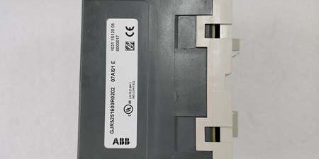
Product Core Brief
- Model: 07AI91, OEM part number GJR5251600R0202
- Brand: ABB
- Series: Advant Controller 31 (AC31) PLC / CS31 distributed remote I/O system
- Core Function: Convert multi-type field analog sensor signals to digital values for AC31 controller process calculation
- Product Type: DIN rail mounted analog input expansion module
- Key Specs: 8 channels configurable in pairs | Supports mA/V/RTD/thermocouple | 1500VAC bus-to-field isolation | 12-bit+sign resolutionNote: Mature production AC31 I/O hardware, new original and new surplus stock available with factory anti-static packaging.
Key Technical Specifications
- Operating supply: 24VDC ±10V, max 0.15A draw, 3W peak power dissipation
- Fieldbus interface: CS31 RS485 slave bus, galvanically isolated from field circuits
- Channel layout: 8 analog inputs, grouped into four independent configurable pairs
- Supported input signal types:Current: 0–20mA, 4–20mAVoltage: ±10V, ±5V, ±500mV, ±50mVRTD: Pt100, Pt1000 (2/3-wire)Thermocouple: J, K, S, R, E, T, N
- ADC resolution: 12-bit plus sign bit
- Full-scale measurement error: ≤ ±0.5% FS
- Galvanic isolation: 1500VAC dielectric separation between CS31 bus side and all field inputs
- Built-in diagnostics: Open sensor wire detection, short-circuit channel fault, out-of-range signal flagging
- Status indicators: 8 individual green channel LEDs, global RUN/FAULT front panel lamps
- Configuration method: DIP switch bank on module front for signal type pairing and CS31 station addressing
- Mechanical mounting: TS35-7.5 / TS35-15 DIN rail per IEC 60715; alternative M4 screw fixed mounting
- Physical dimensions: W120 × H140 × D85 mm; net weight 0.48kg
- Enclosure rating: IP20, plastic ventilated housing
- Operating temperature: 0°C to +55°C full rated performance; linear accuracy derating above +55°C
- Storage temperature: -25°C to +75°C, 5–95% RH non-condensing
- Certifications: CE, UL, DNV, LR, ABS, RoHS compliant
- System compatibility: All AC31 series PLC CPUs and remote I/O stations; incompatible with Freelance 2000, S800, S500, Mod300 platforms
Product Introduction
This unit acts as a universal field sensor interface for AC31 distributed automation racks, eliminating separate single-signal I/O modules by supporting temperature, pressure, flow and level transmitters on one compact chassis. Per-pair DIP switch setup lets users mix thermocouple, RTD and 4–20mA transmitters on the same module without external signal conditioning.
1500VAC isolation blocks ground loop noise common in long plant sensor cables, while continuous wire-break diagnostics push fault data directly to the program without custom ladder logic to monitor sensor integrity. It connects to the controller via two-wire bus to cut field wiring runs for remote tank and pump skids.
QA & Testing SOP (Transparency Building)
- Incoming Inspection: Match serial numbers to ABB component trace databases; inspect terminal screw spring tension, front DIP switch functionality, LED lamp integrity and chassis crack damage; validate unbroken factory static packaging seals for surplus inventory.
- Live Testing: Mount to DIN rail test bench paired with an CPU simulator and calibrated signal generators for mA, voltage, Pt100 and K-type thermocouple signals; run uninterrupted 24-hour cyclic channel scanning with mixed signal pair configurations; log stable 24VDC supply via a Fluke 115 multimeter through full test cycle.
- Electrical Testing: Complete 1500VAC hipot insulation testing between every channel bank and bus ground; pass threshold set above 10MΩ insulation resistance; simulate open sensor leads and channel short circuits to confirm fault flag transmission to the controller.
- Firmware/Config Backup: No user-programmable firmware; photograph DIP switch position layout for standard signal pairs and record factory default channel scaling ranges for commissioning reference.
- Final QC & Packaging: Torque all removable terminal block screws to OEM specified torque values; place unit in static-dissipative foam, attach serialized QC test tag listing measured accuracy values, seal in factory original packaging for shipment.
Installation Pitfalls & Guide (Engineer to Engineer)
❗DIP Switch Misconfiguration Risk: Mismatched DIP switch pair settings assign wrong linearization tables to sensors. Result: Severe scaled process value drift and incorrect HMI readings. Mitigation: Photograph DIP switch positions on the old unit before removal and cross-reference each pair’s signal type against the hardware manual during installation.❗Ground Loop Interference Risk: Tying field sensor shield ground and cabinet PE earth to separate bus bars creates circulating noise currents across isolated channels. Result: Fluctuating analog values and intermittent wire-break false alarms. Mitigation: Connect all sensor cable shields to a single unified chassis ground bar per wiring schematics.❗Overvoltage Field Signal Risk: Feeding unregulated 30V+ test voltage to voltage input channels burns internal ADC front-end resistors. Result: Permanent dead channel without visible LED fault indication. Mitigation: Calibrate all transmitters with a bench multimeter to verify output stays within rated range before wiring to terminals.❗ Bus Termination Omission Risk: Missing 120Ω bus terminator at the farthest remote I/O station generates signal reflection noise. Result: Sporadic loss of all analog measurement data from the module during motor starter switching transients. Mitigation: Install OEM termination plug at both physical endpoints of the RS485 trunk line.❗ESD Dangers: Un-grounded technicians discharge static to exposed DIP switch and terminal PCB traces; field service records show static damage corrupts ADC reference circuits, leading to uncorrectable measurement offset drift with replacement labor costs over $1,100. Mitigation: Hold bare cabinet chassis metal for three full seconds before handling the unit and wear certified anti-static wrist straps during rack work.
4-Step Replacement Guide
- Pre-install: Set the controller to manual hold mode to lock all analog PID control loops; photograph all field sensor wiring terminal assignments and record every DIP switch position on the existing unit.
- Removal: Disconnect upstream bus cable and cut the 24VDC supply circuit breaker; remove all field sensor wiring one pair at a time, then unclip the unit vertically off the DIN rail.
- Install: Clip the new unit fully onto the TS35 DIN rail and fasten chassis PE ground lug to cabinet earth bar; replicate photographed sensor wiring and reset DIP switches to match the original signal pair configurations; reattach bus trunk cable fully seated.
- Power-on Test: Restore 24VDC supply and confirm RUN LED illuminates steady green; inject calibrated test signals to all 8 channels and verify scaled process values match expected engineering units with zero wire-break or short-circuit fault flags; maintain 30 minutes of continuous stable scanning before returning the controller to automatic control mode.
FAQ (Frequently Asked Questions)
Q: Can this unit operate mixed signal types on separate channel pairs at the same time?A: Yes. Each pair of two channels uses independent DIP switch settings, so one pair can run Pt100 temperature probes while adjacent pairs handle 4–20mA pressure transmitters or K-type thermocouples without hardware conflicts.
Q: Does this module support hot-swapping while the bus and 24V supply stay energized?A: Hot-swap is not OEM approved. Removing the unit under live bus power creates RS485 bus contention that drops communication for all remote I/O stations on the trunk. Full 24VDC power isolation is mandatory before removal.
Q: What warranty coverage applies to stocked surplus units?A: All surplus inventory carries a 12-month limited warranty covering factory manufacturing defects only. Damage from misconfigured DIP switches, unmitigated ESD exposure, missing bus termination resistors, and overvoltage field inputs is excluded from warranty claims.
Q: Can individual failed ADC channels be repaired on-site instead of full module swap?A: Field disassembly and component replacement breaks the 1500VAC isolation barrier certification and invalidates factory measurement calibration. Standard maintenance procedure requires full unit replacement for any persistent channel fault or offset drift.
Q: Is this analog input unit rated for Class 1 Div 2 hazardous cabinet mounting?A: No intrinsic safety certification exists for the module assembly. Hazardous zone installations require the full I/O rack to be mounted inside a certified flameproof enclosure to meet area classification standards.
Q: What maximum cable length is allowed for Pt100 RTD sensors connected to the unit?A: Maximum 100m of shielded 3-wire twisted pair cable for Pt100 without measurable resistance offset error; longer runs require 0.5mm² or larger conductor gauges to minimize lead resistance impact on temperature readings.
Q: What long-term upgrade path exists as this unit reaches OEM end-of-support?A: platform migration to modern AC500 PLC replaces this unit with S500 AI523 universal analog input modules. Full cabinet rework, bus removal, and complete analog scaling parameter reconfiguration in Automation Builder software is required for functional parity.




