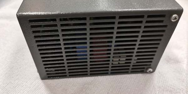
Product Core Brief
- Model: DPW03, full part number P37611-5-8018644 / 8018544M
- Brand: ABB Hartmann & Braun
- Series: Freelance 2000 legacy DCS compact auxiliary power supply
- Core Function: Deliver low-wattage stabilized 24VDC power for small local I/O clusters, HMI panels, and field bus repeaters inside Freelance cabinets
- Product Type: Compact DIN rail mounted switch-mode power supply
- Key Specs: 85–264VAC universal mains input | 24VDC 2A 48W continuous output | OVP, auto-recovery short-circuit, thermal protectionNote: Discontinued legacy DCS auxiliary power hardware, new surplus inventory stocked with factory anti-static packaging.
Key Technical Specifications
- AC input range: 85–264VAC universal single-phase, 50/60Hz
- DC output rating: 24VDC ±1% regulation, 2A continuous, total 48W power
- Minimum full-load conversion efficiency: 90%
- Power factor: ≥0.9 at full rated load
- Integrated protection circuits: Output overvoltage shutdown, constant-current overload foldback, auto-restart short-circuit protection, thermal cutback at high ambient temperature
- Status indicators: Single front-panel green LED for combined mains + output healthy state
- Mechanical mounting: Standard TS35 DIN rail clip-on installation
- Physical dimensions: 63mm W × 105mm H × 130mm D
- Unit mass: 0.60kg
- Enclosure rating: IP20 sealed metal chassis, passive natural convection cooling (no internal fan)
- Operating ambient temperature: -20°C to +60°C full load; linear performance derating above +60°C
- Storage temperature: -40°C to +85°C, 5–95% RH non-condensing
- Safety certifications: CE, UL, TUV, compliant with IEC 61010 industrial control equipment standard
- System compatibility: Exclusive to Freelance 2000 DCS small I/O subracks; incompatible with S800 AC800M, S500 AC500, Mod300 S100 platforms
Product Introduction
This compact switch-mode auxiliary supply delivers steady SELV 24VDC power for low-load auxiliary hardware that does not require the 120W capacity of the larger DPW01 main rack supply. Its wide universal AC input works with both 120V and 230V global plant mains without transformer changes.
Fanless passive ventilation eliminates mechanical wear points and dust ingress risks typical of fan-cooled power supplies. Auto-recovery short-circuit limiting restores normal output automatically after field wiring faults clear, with no manual power cycle required.
QA & Testing SOP (Transparency Building)
- Incoming Inspection: Cross-reference serial numbers against OEM Freelance 2000 component databases; inspect metal chassis for deformation, terminal screw spring tension, LED functionality, and ventilation blockages; validate unbroken factory anti-static packaging seals for surplus inventory.
- Live Testing: Mount the unit to a TS35 DIN rail test bench paired with a variable AC mains source and 48W resistive DC load bank; run continuous 24-hour full-load cycling at both 120VAC and 230VAC input ranges; log steady 24VDC output ripple with a Fluke 115 multimeter through the full test cycle.
- Electrical Testing: Inject overvoltage AC input and DC output short-circuit faults to verify automatic shutdown and self-recovery operation; measure isolation resistance >10MΩ between AC mains terminals and DC output protective earth ground.
- Firmware/Config Backup: No programmable firmware on this unit; photograph front screw terminal pin labeling for mains and DC load wiring for commissioning reference.
- Final QC & Packaging: Torque all AC/DC terminal screws to OEM specified torque values; place unit in static-dissipative foam, attach a serialized QC test tag, then seal in original factory packaging for shipment.
Installation Pitfalls & Guide (Engineer to Engineer)
❗Underrated Mains Circuit Breaker Risk: Fitting a 2A breaker creates nuisance tripping during cold-start inrush current. Result: Unplanned loss of auxiliary field bus and HMI power mid-process run. Mitigation: Size each dedicated AC branch for a minimum 4A slow-blow breaker per unit.❗Overloaded DC Output Risk: Stacking more than four DLM01 mixed I/O modules on a single unit exceeds the 2A continuous rating. Result: Chronic low 24VDC voltage, intermittent Profibus communication timeouts, and LED flicker. Mitigation: Split dense auxiliary I/O loads across separate supplies to balance DC draw.❗Unisolated Ground Loop Risk: Tying AC protective earth and DC 0V common to separate cabinet ground bars creates circulating ground noise. Result: Spontaneous DLM I/O channel flutter and false interlock alarms. Mitigation: Link DC negative return to the same chassis PE ground bar per Freelance wiring diagrams.❗ESD Dangers: Un-grounded technicians transfer static discharge to internal switching semiconductors; field records show static damage causes permanent output foldback with replacement costs exceeding $950 including downtime labor. Mitigation: Maintain continuous chassis ground contact for three full seconds before handling the unit and wear certified anti-static wrist straps during all cabinet work.
4-Step Replacement Guide
- Pre-install: Set all Freelance rack controllers to manual hold mode to freeze discrete and analog control loops; photograph all AC mains L/N/PE wiring and DC 24V/0V load terminal connections on the unit.
- Removal: Disconnect upstream AC circuit breaker and wait 5 minutes for internal bulk capacitors to discharge; remove all DC load wiring one terminal at a time, then unclip the unit vertically from the DIN rail.
- Install: Clip the new unit fully onto the TS35 DIN rail and secure chassis PE ground lug to the cabinet earth bar; replicate all photographed AC and DC terminal wiring connections with matching torque tension.
- Power-on Test: Close the AC breaker and confirm the front-panel LED illuminates solid green; measure 23.5–24.8VDC no-load output voltage, connect full auxiliary load and verify no output voltage drop below 22.8VDC after 30 minutes of continuous operation before returning controllers to automatic control mode.
FAQ (Frequently Asked Questions)
Q: What core load difference separates this unit from DPW01?A: DPW01 delivers 5A / 120W for full main racks populated with CPU and dozens of I/O modules. This unit only supplies 2A / 48W for small auxiliary loads like local I/O clusters, HMI touchscreens, and field bus repeaters.Q: Can this unit run in parallel redundant operation with another unit?A: Parallel redundant stacking is not factory-rated. The internal current-sharing circuitry is absent; mismatched output drift will force one unit to carry 100% of the auxiliary load while the second sits idle, negating redundancy benefits. Deploy separate dedicated supplies for split auxiliary loads instead.Q: Does this unit support hot-swapping while downstream auxiliary hardware stays energized?A: Hot-swap is not approved. Removing the unit while field bus and I/O hardware remains powered creates reverse DC feed into the output stage, which can blow internal power FETs. Full upstream AC isolation and capacitor discharge is mandatory before removal.Q: What warranty coverage applies to stocked surplus units?A: All surplus inventory carries a 12-month limited warranty covering factory manufacturing defects only. Damage from overloaded DC loads, ungrounded ESD exposure, undersized AC breakers, and parallel mismatched power stacking is excluded from warranty coverage.Q: Can a single failed internal power component be repaired on-site instead of full unit swap?A: Field disassembly voids safety isolation certification and compromises passive thermal ventilation design. Standard site maintenance procedure requires full unit replacement for any permanent output foldback or LED fault condition.Q: Is the unit certified for Class 1 Div 2 hazardous area direct cabinet mounting?A: No intrinsic safety certification exists for the unit assembly. Hazardous zone installations require full Freelance rack mounting inside a certified flameproof enclosure to meet area classification standards.Q: What long-term upgrade path exists as this unit reaches OEM end-of-support?A: Freelance 2000 platform migration to System 800xA replaces this unit with standard low-wattage S800 DIN rail 24VDC supplies. Full cabinet rework, auxiliary load splitting, and complete control logic conversion is required to match new power distribution register mapping for AC800M controllers.