
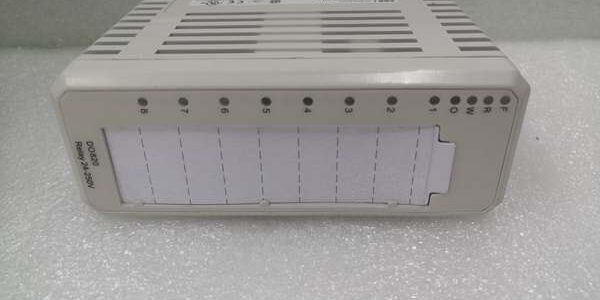
Product Core Brief
- Model: DO820, part number 3BSE008514R1
- Brand: ABB
- Series: S800 I/O for AC800M / System 800xA DCS
- Core Function: Convert DCS logic signals to isolated NO relay contacts to drive AC/DC field actuators without intermediate relays
- Product Type: Compact slide-in digital output I/O module
- Key Specs: 8 fully isolated NO relay channels | 5–250V AC/DC, 3A resistive per channel | OSP fault state programming | 2000VAC channel-to-backplane isolationNote: Active production S800 hardware, new original and new surplus units stocked with factory anti-static packaging.
Key Technical Specifications
- ModuleBus supply: 24VDC, typical power dissipation 2.9W, 140mA 24V draw
- Channel count & form: 8 independent normally open relay outputs
- Continuous contact rating: 3A resistive at 5–250V AC/DC; max 42W DC per channel
- Isolation rating: 2000VAC dielectric test, individual channel-to-channel and channel-to-backplane galvanic separation
- Field wiring limit: 600m maximum shielded twisted pair cable run
- Diagnostic indicators: RUN, FAULT, WARNING, OSP status, individual channel LED status lights
- Built-in supervision: 24V ModuleBus voltage monitoring, configurable fault alarm via DCS bus
- Response latency: Relay pull-in/drop-out time <10ms
- Operating temperature: 0°C to +55°C vertical rack mount; max +40°C tight compact cabinet installations
- Storage temperature: -40°C to +70°C, 5–95% RH non-condensing
- Mechanical dimensions: 45mm W × 102mm D × 119mm H; unit mass 0.23kg
- Compatible termination units: TU811, TU813, TU831, TU836, TU837 series MTUs
- Supported fieldbuses: Local S800 ModuleBus, Profibus DP, Foundation Fieldbus remote I/O stations
Product Introduction
This unit delivers high-power passive relay contacts to eliminate the cost and rack space of auxiliary interposing relays for 220VAC contactors, large solenoid valves, and plant alarm horns. Each channel uses combined optocoupler and relay isolation to block cross-channel EMI noise from motor switching transients.
Onboard OSP logic locks each channel to a user-defined safe on/off state if the controller loses communication or the module faults, preventing unregulated pump/valve movement during critical process trips. It supports both central control room racks and distributed remote field I/O enclosures.
QA & Testing SOP (Transparency Building)
- Incoming Inspection: Match serial numbers to OEM S800 component databases; inspect gold edge connectors for oxidation, PCB conformal coating for peeling, and front LED functionality; validate unbroken factory anti-static packaging seals for surplus inventory.
- Live Testing: Mount to a TU811 MTU on a DIN rail test bench paired with an AC800M simulator and 3A resistive load banks; run continuous 24-hour cyclic channel switching; trigger bus voltage loss to verify WARNING flag reporting; log steady 24VDC supply with a Fluke 115 multimeter through the full test cycle.
- Electrical Testing: Perform 2000VAC hipot insulation testing for every channel against backplane ground; pass threshold set to >10MΩ insulation resistance; inject reversed field voltage and channel short-circuit faults to confirm isolation barriers prevent cross-talk damage.
- Firmware/Config Backup: Record exact module firmware revision via Control Builder M; photograph MTU terminal pin layout and note factory default OSP safe-state parameters for commissioning reference.
- Final QC & Packaging: Torque all MTU terminal screws to OEM specified torque values; place unit in static-dissipative foam, attach a serialized QC test tag, then seal in original factory packaging for shipment.
Installation Pitfalls & Guide (Engineer to Engineer)
❗Firmware Rev Mismatch Risk: Outdated AC800M controller firmware fails to parse OSP and bus supervision registers. Result: Missing fault alarms and undefined channel states during comms loss. Mitigation: Flash matching validated firmware revisions to the controller before rack power-up and archive matched firmware sets to plant engineering servers.❗Overloaded Relay Contacts Risk: Driving inductive loads exceeding 3A without external freewheeling diodes causes contact welding after thousands of switching cycles. Result: Stuck valve or pump states that force unplanned process shutdowns. Mitigation: Add external flyback diodes for all inductive loads and install interposing relays for loads above 3A continuous draw.❗MTU Incompatibility Risk: Mating the module to non-TU81x/TU83x termination bases misaligns edge connector pinouts and exposes internal circuits to unregulated field voltage. Result: Burned relay driver semiconductors and permanent unit failure. Mitigation: Only pair with OEM TU811, TU813, TU831, TU836, or TU837 terminal assemblies.❗Cross-Channel Common Wiring Error: Sharing return wiring between isolated channels breaks galvanic separation. Result: Spontaneous relay actuation during large motor contactor switching. Mitigation: Run fully isolated return wiring for every channel per the S800 MTU wiring schematic.❗ESD Dangers: Un-grounded technicians transfer static discharge to the PCB’s delicate optocoupler circuits; field records show static damage renders entire channels non-functional, with replacement costs exceeding $1,800 including downtime labor. Mitigation: Maintain continuous chassis ground contact for three full seconds before handling the module and wear certified anti-static wrist straps during all rack work.
4-Step Replacement Guide
- Pre-install: Set the AC800M controller to manual hold mode to freeze all discrete interlock states; photograph all field wiring connections on the MTU and record configured OSP safe-state parameters in Control Builder M.
- Removal: Slide the unit vertically upward out of the termination base without bending gold edge pins; leave all field wiring secured to the MTU to avoid full re-termination.
- Install: Align the new unit’s rear edge connector with the MTU slot and seat fully until the retention latch clicks; replicate all photographed wiring connections and reapply saved OSP fault-state parameters to match the original process safety logic.
- Power-on Test: Restore 24VDC ModuleBus supply; force each channel on/off via DCS simulator to verify consistent relay actuation and matching front-panel LED status; simulate bus voltage loss to confirm WARNING alarm reporting; run 30 minutes of idle channel polling with zero fault flags before returning the controller to automatic control mode.
FAQ (Frequently Asked Questions)
Q: What core functional difference separates this unit from DO810 and DO814 transistor outputs?A: DO810/814 are 24VDC sinking/sourcing transistor outputs limited to 0.5A and only compatible with low-voltage DC loads. This unit uses passive isolated relay contacts rated for universal 5–250V AC/DC at 3A, eliminating interposing relays for high-voltage contactor and valve circuits.
Q: Does the unit support hot-swapping while the termination base remains energized?A: Mechanical hot-swap is hardware rated for the platform, but the relay channels will drop state momentarily during removal/insertion. Critical safety interlock loops require manual hold mode activation on the controller prior to module exchange to prevent unplanned equipment actuation. Hot-swap only protects internal semiconductors from power transients, not field load continuity.
Q: What warranty coverage applies to stocked surplus units?A: All surplus inventory carries a 12-month limited warranty covering factory manufacturing defects only. Damage from overloaded contact loads, unmitigated inductive flyback spikes, ESD exposure, incompatible MTUs, or firmware mismatch faults is excluded from warranty coverage.
Q: Can individual failed relay channels be repaired on-site instead of full module swap?A: Field disassembly and component replacement void isolation certification and degrade the 2000VAC dielectric rating required for plant safety compliance. Standard site maintenance procedure requires full unit replacement for any single failed channel.
Q: Can multiple of these units share a single 24VDC ModuleBus power feed in one rack?A: Shared bus power is permitted only if the power supply maintains a minimum 20% current headroom above the total combined rack draw. Independent auxiliary bus feeds are recommended for racks with six or more units to eliminate voltage sag during mass simultaneous relay switching events.
Q: Is the unit certified for Class 1 Div 2 hazardous area direct cabinet mounting?A: No intrinsic safety certification exists for the module assembly. Hazardous zone installations require full rack mounting inside a certified flameproof enclosure to meet area classification standards.
Q: What long-term upgrade path exists as this unit reaches OEM end-of-support?A: The unit remains standard hardware for new System 800xA deployments. Full platform migration to AC900 and S900 I/O requires complete cabinet rework, field wiring re-termination, and full control logic conversion to match S900 relay module register mapping.




