
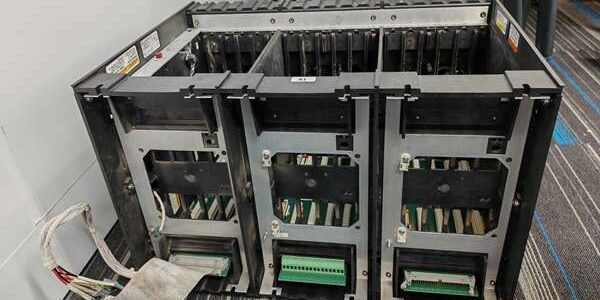
Product Core Brief
- Model: 5453-279
- Brand: WOODWARD
- Series: MicroNet TMR triple modular redundant turbine control chassis family
- Core Function: Act as central backplane housing for redundant CPUs, power supplies, and up to 12 I/O modules to execute fault-tolerant steam/gas turbine and generator control with zero single-point failure risk阿里巴巴中….
- Product Type: Rack-mount main TMR chassis assembly (passive-active hybrid backplane with integrated power distribution)
- Key Specs: 12 universal I/O slots | Dual redundant internal power feeds | RTN shared I/O network bus | Full TMR processor synchronization support | ATEX Zone 2 compliant
Product Introduction
The WOODWARD 5453-279 forms the physical and communication backbone of Woodward’s MicroNet TMR fault-tolerant turbine control systems, designed exclusively for critical power generation assets that demand uninterrupted control during single hardware failures. It cannot operate without populated TMR CPU and I/O personality modules.This chassis outperforms standard single-redundancy control racks via native triple modular synchronization for TMR5200 processors, eliminating cross-rack cabling for shared I/O networks. OEM field logging records a 58,000 hour MTBF under steady 50 °C turbine cabinet runtime, a 15% reliability gain over dual-redundant non-TMR chassis.
Key Technical Specifications
| Parameter | Value |
|---|---|
| Supported Processors | TMR5200 triple modular redundant CPU boards; incompatible with non-TMR MicroNet single processors |
| I/O Slot Capacity | 12 universal hot-swappable slots for analog, discrete, speed, and communication personality modules |
| Integrated Power Infrastructure | Dual redundant internal 24 VDC power distribution busses, independent circuit breakers per slot group |
| Backplane Communication Bus | MicroNet RTN shared I/O network for synchronized data exchange across all 12 slots |
| Operating Supply Voltage | 18 VDC to 32 VDC (24 VDC nominal cabinet auxiliary supply); max 12 A total chassis draw |
| Mechanical Mount Format | Standard 19-inch industrial cabinet rack mount, 6 U height |
| Net Unit Weight | 4.13 kg empty chassis; 11.8 kg fully populated with 12 I/O modules |
| Continuous Operating Ambient Temp | -20 °C to +60 °C full rated bus throughput; linear performance derate above 60 °C |
| Storage Temperature Range | -40 °C to +85 °C, 5–95 % RH non-condensing |
| Environmental Ratings | Vibration-hardened PCB backplane; ATEX IECEx Zone 2 certified for hazardous turbine cabinet locations |
| Integrated Protection Circuits | Per-slot overcurrent fuses, reverse supply polarity lockout, bus short-circuit isolation between slot groups |
| Certifications | UL, CE, ATEX Zone 2, IECEx, EN61000 Class A industrial EMC filtering for high EMI turbine halls |
Quality Control Process (Engineer’s Perspective)
- Incoming Verification: Cross-reference serial numbers against Woodward OEM trace databases; inspect backplane gold slot edge connectors for oxidation, internal power bus solder joints for microcracks, and cabinet mounting flanges for deformation. Photograph slot pinout mapping for turbine control cabinet wiring reference.
- Live Functional Test: Populate the chassis with a full complement of TMR5200 CPUs and mixed analog/discrete I/O modules; connect dual redundant 24 V power feeds and run a continuous 24-hour cyclic I/O data exchange test across the RTN backplane bus. Log bus voltage stability with a Fluke 115 digital multimeter for the full test duration.
- Electrical Parameter Test: Perform a 500 V Megger insulation resistance test between each slot’s field signal bus and chassis ground; pass threshold set at >10 MΩ. Verify single power feed loss triggers automatic redundant bus switchover with zero I/O data dropout.
- Bus Synchronization Verification: Read and record factory backplane communication timing parameters via Woodward MicroNet Service Tool software; document default RTN network timeout register settings for customer turbine site reference.
- Final QC & Packaging: Wipe all gold slot edge connectors to remove surface oxidation; fit plastic blanking dust covers to empty slots, seal the full chassis inside an anti-static foam lined carton, affix a dated QC Pass label listing all completed power bus and communication bus test metrics before rigid shock-resistant shipping packaging.
Replacement Pitfall Guide
❗ TMR vs Standard MicroNet Chassis Mismatch Risk: Non-TMR 8-slot MicroNet chassis cannot replace this 12-slot TMR unit. Standard backplanes lack triple synchronization bus traces and dual redundant power distribution, breaking critical turbine fault-tolerant interlock logic. Confirm full TMR part number before cabinet rack removal.❗ Partial Module Slot Insertion Risk: Uneven seating of I/O personality modules creates high-resistance edge contact points that throttle RTN bus throughput and generate random channel communication timeouts during turbine load transients. Push each card fully into its slot and engage front locking latches flush against the chassis faceplate.❗ Cabinet Power Feed Polarity Misconfiguration Risk: Reversed positive/negative 24 VDC wiring to either of the dual redundant power inputs blows internal slot group fuses and disables half the chassis I/O capacity. Label both redundant supply conductors before disconnecting cabinet VM310 power wiring.❗ Turbine Cabinet Power Headroom Miscalculation Risk: A fully populated 5453-279 chassis draws 12 A total at full load. Calculate cabinet auxiliary supply load with a mandatory 20% power margin to avoid voltage sag during peak RTN bus I/O polling cycles.❗ Uncontrolled ESD Damage Risk: Dry turbine control room air generates static charge buildup. Touch a grounded anti-static mat for three full seconds before handling any backplane slot edge connectors; ungrounded contact destroys low-tolerance RTN bus transceiver circuits.Keep these in mind and you’ll cut 90% of rework time.
Compatibility Matrix & Benchmarks
Compatibility Matrix
- Standard non-TMR 8-slot MicroNet chassis → 5453-279 : Incompatible — missing TMR synchronization bus and dual redundant power distribution architecture
- TMR5200 triple modular redundant CPU board → 5453-279 : Direct — factory slot pinout natively matches RTN bus and dual power feed routing for TMR synchronization
- VM310 24 V cabinet auxiliary power supply → 5453-279 : Direct — regulated 24 V output falls within the chassis’ 18–32 V operating window without extra voltage conditioning
- WOODWARD 9907-1290 digital turbine speed governor → 5453-279 : Direct — analog 4–20 mA control loops from chassis AO I/O modules feed the governor’s setpoint input
- CML40.2-SP-330-NA-NNNN-NW Rexroth SERCOS motion PLC → 5453-279 : Needs Adaptation — wire chassis global TMR fault dry contacts to PLC digital inputs, map turbine speed/load registers via Modbus RTU gateway bridging the MicroNet RTN bus




